lumenstudio
™
software user manual
lumenstudio
™
software user manual
6
7
III Installation
The Lumentouch 2.0 and Lumencue are stand alone DMX controllers which are perfect for any DMX application. They
feature touch sensitive controls, 2 full universes of DMX control, astronomical clock mechanisms, remote control capabilities
and much more. Lumenstudio is your direct link to accessing the full potential of your controller with an intuitive, user friendly
interface that will have you programming your own shows quickly and easily.
The Lumentouch interface must be connected to a computer with Lumenstudio installed. Connection could be with
the mini USB cable provided, or an ethernet connection over a network. Drivers will be installed automatically when
first connected if needed.
The controller can be programmed from a PC using the software available on our website.
Refer to the corresponding user manual for more information. The firmware can be updated using the Hardware
Manager which is included with the programming software.
Lumenstudio Software and hardware (Windows)
http://www.lumenpulse.com/en/product/128/lumentouch-20
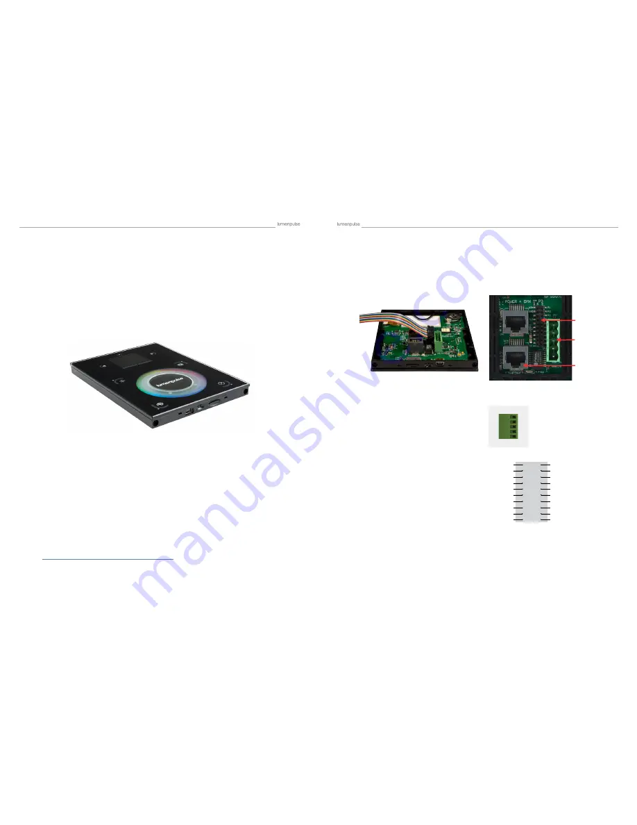
All connections (DMX, power, ports…) are made with the rear connectors. The 6V DC power supply must be con-
nected to the 2 Power pins, and the 1st DMX universe to the 3 DMX pins of the main 5pin connector block. Power
can also be provided by POE (Power over Ethernet) via the Power + DMX RJ-45 connection. Using the EXT Port
connection, this interface has 8 ports (1 to 8) to trigger scenes. To use the input ports, you must create a connection
between the Ground pin and the ports. This EXT Port connection also adds the capabilities of RS232 and access to
the second Universe of DMX.
Wire Color Code for Lumentouch 2.0 (DE-3) EXT Port Connector
NOTE: connector should be installed with ribbon facing Ethernet port
Pin
Color
Port
P1
Brown1 RS232 TX
P2
Red1
GND DMX
P3
Pink1
RS232 RX
P4
Yellow1 DMX U1 (-)
P5
Green1 Port8
P6
Blue1
DMX U1 (+)
P7
Purple1 Port7
P8
Grey1
DMX U2 (-)
P9
White1 Port6
P10
Black1 DMX U2 (+)
P11
Brown2 Port5
P12
Red2
Relay
P13
Pink2
Port4
P14
Yellow2 3.3V
P15
Green2 Port3
P16
Blue2
IR RX
P17
Purple2 Port2
P18
Grey2
GND
P19
White2 Port1
P20
Black2 VIN
EXT Port Connector Pin Detail
5 Pin Connector Block Detail
Power + DMX with the connector block
3.2. Connections
VIN
GND
IR_RX
3.3V
RELAY
DMX2+
DMX2 -
DMX1+
DMX1 -
GND_DMX
20
18
16
14
12
10
8
6
4
2
19
17
15
13
11
9
7
5
3
1
PORT 1
PORT 2
PORT 3
PORT 4
PORT 5
PORT 6
PORT 7
PORT 8
RS232 RX
RS232 TX
c l w ?
J
cl w
?J
POWER
DC +
POWER
Ground
DMX
Ground
DMX -
DMX +
EXT Port Connector
5 Pin Connector
Ethernet Port
3.1. Programming the Controller


