background image

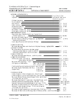
The model name, unique 4- or 5- digit serial number and 
certification markings of the light engine are carried on a 
label a

xed to the rear panel.  Performance specifications 

for individual light engines are listed on the certificate of 
conformance included with the shipping documents e-
mailed to the customer (Figure 1).

3.2  Installation 

NOTE: Any end-product/system incorporating or coupled 
to a Lumencor Light Engine shall be fully evaluated to 
verify all applicable safety and regulatory compliance 
requirements prior to use.

When setting the AURA Light Engine up for use, place the 
unit on a hard surface and avoid blocking or restricting 
airflow at the air inlet (front panel; Figure 3) or exhaust 
ports (rear panel) on the enclosure.  Restricting the 
airflow will cause the unit to operate at elevated 
temperatures and will result in decreased product life 
and/or premature failure.

The AURA Light Engine must be operated in a non-
condensing environment (dew point <10ºC with controlled 
ambient temperature <30º C). Thermal overload protection 
is provided by the on-board computer in conjunction with 
an on-board temperature sensor.  If the internal 
temperature registered by the sensor exceeds 50°C 

or

 the 

fan rotor is stopped, all light output channels automatically 
turn OFF and are locked in this state until the internal 
temperature is below 50°C and/or the fan restarts.  The 
current reading of the on-board temperature sensor is 
displayed on the front panel status display (Figure 3) and in 
the GUI (Figure 5, right).

Connect the DC power supply to a grounded AC wall 
outlet using the power cord supplied with the light engine.  
Connect the DC output to the 6-pin receptacle on the front 
of the light engine (Figure 3).  Turn the light engine on 

AURA Light Engine Manual 57-10011

9

Figure 3. 

 AURA Light Engine front panel.

Status 

DC 
power 
input

Output 
Coupler, 
LLG

Master 
power 

Air intake

Figure 4. 

 AURA Light Engine rear panel.

Remote interlock 
connector (with 
jumper installed)

Summary of Contents for AURA Light Engine

Page 1: ...Lumencor Light Engine Manual AURA Light Engine AURA Light Engine Manual 57 10011 lumencor com...

Page 2: ...ication EN 61010 1 2010 CE Marking Low Voltage Directive 2014 35 EU EMC Directive 2014 30 EU RoHS Directive 2011 65 EU 2015 863 EU REACH Regulation EC No 1907 2006 EC EU Declarations of Conformity can...

Page 3: ...Precautions and Warnings 3 Installation and Operating Instructions 4 Light Output Characteristics 5 Operational Specifications 6 Routine Maintenance and Trouble Shooting 7 Customer Support 8 Warranty...

Page 4: ...utput over time The light sources within the AURA Light Engine are controlled by an on board microprocessor operating Lumencor firmware accessed via one of two serial interfaces USB RS 232 or TCP The...

Page 5: ...ce de la protection o erte par l appareil Conserver toutes les instructions de s curit Safety Definitions D finitions relatives la s curit Warning Statements identify conditions or practices that coul...

Page 6: ...t sup rieure celle de la majorit des appareils d clairage disponibles dans le commerce et est con ue pour un raccordement direct un microscope ou autre appareil de bioanalyse Warning DO NOT turn on th...

Page 7: ...may damage your light engine Attention NE PAS placer de liquide sur la source lumineuse Les liquides renvers s peuvent endommager la source lumineuse Caution DO NOT drop the light engine It contains g...

Page 8: ...lock jumper Figure 2 6 Quickstart Guide instruction document 85 10049 AURA Light Engine Manual 57 10011 8 AC Power Cords Region Part Number North America 29 10002 Europe 29 10005 United Kingdom 29 100...

Page 9: ...he AURA Light Engine must be operated in a non condensing environment dew point 10 C with controlled ambient temperature 30 C Thermal overload protection is provided by the on board computer in conjun...

Page 10: ...oard computer takes about 30 seconds after the master power switch is turned on When initialization is complete the status indicator display Figure 3 will activate The Key Control Figure 3 must be in...

Page 11: ...GE DISTANCE PEUT ENTRA NER UN COMPORTEMENT ANOMAL ET OU ENDOMMAGER LES PRODUITS WARNING Prior to turning the light output on be sure the output end of the liquid light guide or optical fiber is safely...

Page 12: ...Ensure that the distal end of the light guide or optical fiber is safely directed into an enclosed optical path e g microscope epi illuminator or a beam dump before turning the light output on If the...

Page 13: ...tal factors in photometric and quantitative imaging applications where reproducibility and accuracy are essential To use power regulation a desired power reference value in milliwatts is entered in th...

Page 14: ...AURA Light Engine control mode change the setting by holding down the MODE button on the pod until the light engine selection menu appears Move the cursor to AURA in the selection menu by turning the...

Page 15: ...y on or by turning on additional sources commands will be rejected To clear the error condition reduce intensities of sources that are on or turn o additional sources Light source outputs are refined...

Page 16: ...ate of conformance for reference In the event that the light engine is sold the certificate of conformance should be transferred to the new owner Certificates of conformance are also recorded in Lumen...

Page 17: ...to 10 000 feet 3 048 meters Non operating 0 to 45 000 feet 13 176 meters Dew Point Operating 32 to 59 F 0 to 15 C Dimensions Size W x L x H 145 mm x 263 mm x 203 mm 5 7 in x 10 4 in x 8 0 in Weight 6...

Page 18: ...uide must be inserted in light output receptacle 3 Remote interlock jumper must be inserted in rear panel 4 External gate jumper must be inserted in front panel Figure 3 Unusually weak fluorescence si...

Page 19: ...onditions consistent with the specifications given in Section 5 and observing all the Precautions and Warnings notified in Section 2 This warranty does not extend to light engines that have been subje...

Reviews: