7.31
Model 644E-42/944E-42
Rev. 6/04
Engine: Cummins 4BT 3.9, B4.5T and QSB 4.5T
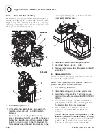
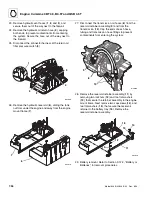
3. Loosen the lower clamp (7) attaching the flex
pipe (8) to the muffler (9). Loosen and remove the
two screws (10) securing the bracket (11) to the
muffler (9). Remove the four screws (12 and 13), six
washers (14 and 15) and two nuts (16) securing the
muffler (9) to the frame. Remove the muffler.
4. Loosen the upper clamp (17) on the flex pipe, and
remove the flex pipe (8). Loosen the V-band
clamp (18) securing the exhaust pipe (19) to the
turbo outlet (20). Remove the exhaust pipe.
7.9.2
Exhaust System Installation
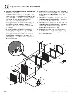
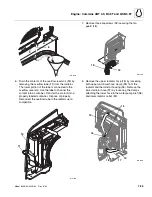
1. Install the turbo outlet exhaust pipe (19) onto the
engine turbocharger outlet (20). Install, but do not
tighten, the V-band clamp (18) around the turbo
outlet exhaust pipe. Align the elbow (23) (bend)
portion of the exhaust pipe, so that the pipe is
parallel (24) with the frame of the vehicle. Secure the
exhaust pipe (17) to the Turbo outlet (18) by
tightening the V-band clamp (16). Torque the V-band
clamp to 4-5 lb-ft (6-7 Nm).
2. Install the muffler bracket (11) to the frame. Apply
Loctite® 242 (blue) to the screws and loosely secure
bracket in place with two screws (12), four washers
(14) and two nuts (16).
3. Slide the front muffler bracket (21) onto the hanger
on the frame (22). Apply Loctite® 242 (blue) to the
screws and loosely secure front of muffler in place
with two screws (13) and washers (15).
4. Lift the rear of the muffler into place. Apply Loctite®
242 (blue) to the screws and secure rear of the
muffler to the bracket with two screws (10). Torque
screws to 19-38 lb-ft (26-52 Nm).
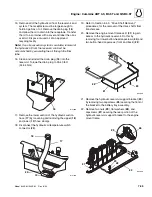
5. Slide the flex pipe (8) between the muffler (9) and
the exhaust pipe (19). Align the flex pipe (8) with the
muffler (9) and the exhaust pipe (19). Correct
alignment between the flex pipe (8) and exhaust
pipe (19) will have been achieved when the center
lines (25) and (26) of each is aligned. This must be
done when viewing the exhaust system from the
rear (25) and side (26) of the vehicle. Secure the
muffler (9) and muffler bracket (11) to the frame.
Torque screws to 19-38 lb-ft (26-52 Nm).
6. Secure the flex pipe (8) to the muffler (9) and the
exhaust pipe (19). Torque the clamp bolts to
45-60 lb-ft (61-81 Nm).
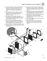
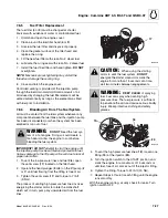
7. If the vehicle has dual batteries, connect both
negative battery cables (1 and 2) to both batteries.
Connect the lower negative battery cable (1) to the
negative (-) terminal on the lower battery (3). Swing
the upper battery box (6) in and make sure that the
lip (5) on the upper battery box slides below the
knob (4). Secure in place with the knob (4).
MU2072
7
8
17
12
13
14
9
15
16
18
19
20
Front
10
11
21
22
MU5411
23
24
25
26
Rear View
Side View
Summary of Contents for 944E-42
Page 1: ......
Page 2: ......
Page 14: ...Safety Practices 1 8 Model 644E 42 944E 42 Rev 6 04 This Page Intentionally Left Blank...
Page 102: ...Boom 3 56 Model 644E 42 944E 42 Rev 6 04 This Page Intentionally Left Blank...
Page 139: ...4 37 Model 644E 42 944E 42 Rev 6 04 Cab and Covers This Page Intentionally Left Blank...
Page 144: ...Cab and Covers 4 42 Model 644E 42 944E 42 Rev 6 04 This Page Intentionally Left Blank...
Page 265: ...8 15 Model 644E 42 944E 42 Rev 6 04 Hydraulic System This Page Intentionally Left Blank...
Page 269: ...8 19 Model 644E 42 944E 42 Rev 6 04 Hydraulic System This Page Intentionally Left Blank...
Page 273: ...8 23 Model 644E 42 944E 42 Rev 6 04 Hydraulic System This Page Intentionally Left Blank...
Page 277: ...8 27 Model 644E 42 944E 42 Rev 6 04 Hydraulic System This Page Intentionally Left Blank...
Page 281: ...8 31 Model 644E 42 944E 42 Rev 6 04 Hydraulic System This Page Intentionally Left Blank...
Page 285: ...8 35 Model 644E 42 944E 42 Rev 6 04 Hydraulic System This Page Intentionally Left Blank...
Page 289: ...8 39 Model 644E 42 944E 42 Rev 6 04 Hydraulic System This Page Intentionally Left Blank...
Page 293: ...8 43 Model 644E 42 944E 42 Rev 6 04 Hydraulic System This Page Intentionally Left Blank...
Page 297: ...8 47 Model 644E 42 944E 42 Rev 6 04 Hydraulic System This Page Intentionally Left Blank...
Page 301: ...8 51 Model 644E 42 944E 42 Rev 6 04 Hydraulic System This Page Intentionally Left Blank...
Page 407: ...8 157 Model 644E 42 944E 42 Rev 6 04 Hydraulic System This Page Intentionally Left Blank...
Page 425: ...8 175 Model 644E 42 944E 42 Rev 6 04 Hydraulic System This Page Intentionally Left Blank...
Page 501: ...8 251 Model 644E 42 944E 42 Rev 6 04 Hydraulic System MT1950 2 3 4 5 6 7 8 5 5...
Page 507: ...8 257 Model 644E 42 944E 42 Rev 6 04 Hydraulic System MT1950 1 2 3 4 5 6 7 4 4...
Page 508: ...Hydraulic System 8 258 Model 644E 42 944E 42 Rev 6 04 This Page Intentionally Left Blank...
Page 525: ...9 17 Model 644E 42 944E 42 Rev 6 04 Electrical System This Page Intentionally Left Blank...
Page 554: ...Electrical System 9 46 Model 644E 42 944E 42 Rev 6 04 This Page Intentionally Left Blank...
Page 759: ...10 3 Model 644E 42 944E 42 Rev 6 04 Stabil TRAK System This Page Intentionally Left Blank...
Page 765: ...10 9 Model 644E 42 944E 42 Rev 6 04 Stabil TRAK System This Page Intentionally Left Blank...
Page 785: ...10 29 Model 644E 42 944E 42 Rev 6 04 Stabil TRAK System This Page Intentionally Left Blank...
Page 800: ...Stabil TRAK System 10 44 Model 644E 42 944E 42 Rev 6 04 This Page Intentionally Left Blank...
Page 832: ...Transfer Carriage 11 32 Model 644E 42 944E 42 Rev 6 04 This Page Intentionally Left Blank...
Page 840: ...12 8 Model 644E 42 944E 42 Rev 6 04 Index...
Page 841: ...Accident Prevention Tags OS2180 8990403 Origin 5 00 Accident Prevention Tags...
Page 842: ...Accident Prevention Tags OS2180 8990403 Origin 5 00...
Page 843: ......
Page 844: ......

