5. ROUTER DESIGN
Example of connecting devices with serial interface to the USB:
Figure 23: Connection PLC to the router
Example of connecting of USB flash disk to the USB:
Figure 24: Connection flash memory to the router
5.8.9
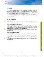
I/O Port
Panel socket 3pin.
Pin
Signal mark
Description
Data flow direction
1
BIN0
Binary input
Input
2
GND
Signálová zem
3
OUT0
Binary output
Output
Table 10: Connection of I/O port
Figure 25: I/O connector
20
19-06-15
LUCOM GmbH * Ansbacher Str. 2a * 90513 Zirndorf * Tel. 09127/59 460-10 * Fax. 09127/59 460-20 * www.lucom.de

