LIST OF FIGURES
List of Figures
1
Contents of package . . . . . . . . . . . . . . . . . . . . . . . . . . . . . . . . .
4
2
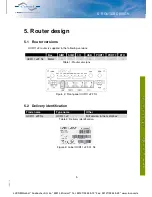
Front panel UCR11 v2F SL . . . . . . . . . . . . . . . . . . . . . . . . . . . . .
5
3
Label UCR11 v2F-01 SL . . . . . . . . . . . . . . . . . . . . . . . . . . . . . . .
5
4
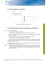
Basic dimensions of metal box . . . . . . . . . . . . . . . . . . . . . . . . . . .
8
5
Space around antennas . . . . . . . . . . . . . . . . . . . . . . . . . . . . . . .
9
6
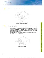
Cable routing . . . . . . . . . . . . . . . . . . . . . . . . . . . . . . . . . . . . .
9
7
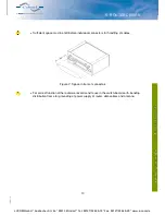
Space in front of connectors . . . . . . . . . . . . . . . . . . . . . . . . . . . . .
10
8
Default position of DIN holder . . . . . . . . . . . . . . . . . . . . . . . . . . . .
11
9
Removing from the DIN rail . . . . . . . . . . . . . . . . . . . . . . . . . . . . .
11
10
Front panel UCR11 v2F SL . . . . . . . . . . . . . . . . . . . . . . . . . . . . .
12
11
Power connector . . . . . . . . . . . . . . . . . . . . . . . . . . . . . . . . . . .
14
12
Connection of power supply connector . . . . . . . . . . . . . . . . . . . . . . .
14
13
Connection of power supply . . . . . . . . . . . . . . . . . . . . . . . . . . . . .
14
14
External antenna . . . . . . . . . . . . . . . . . . . . . . . . . . . . . . . . . . .
15
15
Connecting of the antenna . . . . . . . . . . . . . . . . . . . . . . . . . . . . . .
15
16
Ejected SIM holder . . . . . . . . . . . . . . . . . . . . . . . . . . . . . . . . . .
16
17
Ethernet connector . . . . . . . . . . . . . . . . . . . . . . . . . . . . . . . . . .
17
18
Connection of ethernet cable . . . . . . . . . . . . . . . . . . . . . . . . . . . .
17
19
Example of router connection . . . . . . . . . . . . . . . . . . . . . . . . . . . .
17
20
PORT1 cable connection
. . . . . . . . . . . . . . . . . . . . . . . . . . . . . .
18
21
PORT2 cable connection
. . . . . . . . . . . . . . . . . . . . . . . . . . . . . .
19
22
USB connector . . . . . . . . . . . . . . . . . . . . . . . . . . . . . . . . . . . .
19
23
Connection PLC to the router . . . . . . . . . . . . . . . . . . . . . . . . . . . .
20
24
Connection flash memory to the router . . . . . . . . . . . . . . . . . . . . . . .
20
25
I/O connector . . . . . . . . . . . . . . . . . . . . . . . . . . . . . . . . . . . . .
20
26
Connection of I/O cable . . . . . . . . . . . . . . . . . . . . . . . . . . . . . . .
21
27
Connection of input and output to the router . . . . . . . . . . . . . . . . . . . .
21
28
Router reset . . . . . . . . . . . . . . . . . . . . . . . . . . . . . . . . . . . . . .
22
29
Router connection . . . . . . . . . . . . . . . . . . . . . . . . . . . . . . . . . .
23
iv
19-06-15
LUCOM GmbH * Ansbacher Str. 2a * 90513 Zirndorf * Tel. 09127/59 460-10 * Fax. 09127/59 460-20 * www.lucom.de


