Lucent Technologies CIB 7102 Installation Instructions Manual Download Page 6

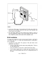
Lift the base and push the wall support through the slots until the
tabs click into place. Turn the base over.

Tab B

Tab A

Bottom

of Base

FIGURE 6

2

3

4

5

6

7

8

9

Locate a modular wall jack within 7 feet of where you want to mount
the terminal.

If the terminal will be mounted on a plaster or sheetrock wall, locate a
wall stud nearest the desired mounting site. Center the base on the
stud. Use the screw holes in the four corners of the base to mark
screw locations on the wall over the stud. If necessary, drill out the
holes in the base to make them larger.

NOTE:  If the terminal is to be mounted on any other surface, use
appropriate mounting hardware.

Using a 1/8” drill bit, drill a hole at each of the 4 marked screw loca-
tions on the wall.

Insert one sleeve into each of the 4 drilled holes. Use a hammer to
tap each sleeve until it is flush with the wall.

With the base flush against the wall, line up the holes in the base with
the sleeves. Insert screws through the base into the top 2 holes and
partially thread the screws into the sleeves. Insert the other 2 screws
into the lower 2 holes.

Tighten all 4 screws. The wall mount should now be fastened
securely.

Flex the plastic window covering the telephone number card and
remove it. Put the plastic window and card aside. Loosen the screw
beneath the number card. Remove the screw and lift out the
retainer.

Rotate the retainer and replace it so that the smooth side faces up.
Replace the screw. Write or type your telephone number on the

iss 1, 7102A VT-5

Summary of Contents for CIB 7102

Page 1: ...CIB 7102 Voice Terminal Installation Instructions CIB 7102 Issue 1...

Page 2: ...tem 85 Terminal and 1 2 3 4 Adjuncts Installation and Test 555 015 104 AT T System 75 System 75 XE and System 85 Terminal and Adjuncts Reference Manual 555 015 201 AT T System 75 7102A Voice Terminal...

Page 3: ...the base Turn the base over so the rubber feet are down Insert the tabs labeled A and B on the desk support into the corresponding slots on the base Desk Support Tab A Tab B B a s e FIGURE 2 Hold the...

Page 4: ...that the terminal tabs fit securely in the 3 stand mounting slots Ringer Volume Control Desk Support Rubber Feet FIGURE 4 Locate a modular wall jack within 7 feet of your desk or table 2 3 Insert one...

Page 5: ...s codes card and the faceplate cover Wall Installation To mount your terminal on a wall you may need a hammer a drill and a 1 8 drill bit four 1 8 x 2 screws and mounting sleeves cutting pliers and a...

Page 6: ...Using a 1 8 drill bit drill a hole at each of the 4 marked screw loca tions on the wall Insert one sleeve into each of the 4 drilled holes Use a hammer to tap each sleeve until it is flush with the w...

Page 7: ...n the wall mount Arrange the line cord so that it runs down the wall behind the terminal Then slide the terminal down so that the tabs fit securely into the slots of the wall mount Controls and Displa...

Page 8: ...and conditions specified in your agreement with AT T apply Hearing Aid Compatibility This terminal is compatible with inductively coupled hearing aids prescribed by the Federal Communications Commissi...

Reviews: