card. Replace the card and plastic window. Install the access codes
card and the faceplate cover.
H a n d s e t
R e t a i n e r
H a n d s e t
R e t a i n e r
H a n d s e t R e t a i n e r
S c r e w
R e m o v e r
H a n d s e t
R e t a i n e r
After
R o t a t i o n
H a n d s e t
R e t a i n e r
S c r e w
FIGURE 7
10
11
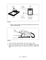
Follow the instructions in steps 2 through 4 of the DESK INSTALLA-
TION section for connecting the line cord and the handset cord and
preparing the terminal for use.
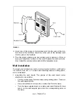
Hold the terminal so that the mounting tabs fit just above the mount-
ing slots on the wall mount. Arrange the line cord so that it runs
down the wall behind the terminal. Then, slide the terminal down so
that the tabs fit securely into the slots of the wall mount.
Controls and Display
1
Set the ringer volume control to the midpoint so you will be able to
hear the terminal ring.
Testing
1
Pick up the handset and listen for the dial tone. It can take a few
moments for the switch to initially recognize the terminal and supply
dial tone.
●
●
If you do not hear a dial tone, depress the switchhook several
times and check that both cords are connected firmly at both
ends.
If you still do not hear a dial tone, contact your company’s
telecommunications manager.
iss 1, 7102A VT-6


