


User manual of POE-SW1602/POE-SW2402
8
1.3
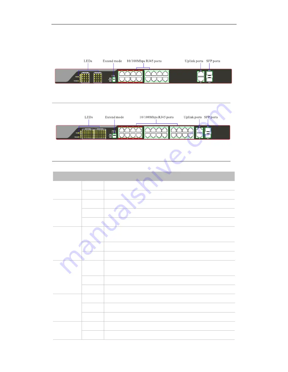
Front Panel
Figure 1.1 POE-SW1602
Figure 1.2 POE-SW2402
Table 1.1 Description of LEDs
LED
Status
Description
PWR
Solid
The device is connected to the power supply properly.
Off
The device is connected improperly or not connected to the power supply.
LINK/ACT
Solid
The corresponding port is connected properly.
Blinking
The corresponding port is transmitting data.
Off
The corresponding port is connected improperly or not connected.
POE STATUS
Solid
The corresponding port is connected with a PD (Powered Device) and powers
the PD properly.
Blinking
The PoE output of the corresponding port exceeds 30W.
Off
The corresponding port is no PoE power output or no PD connected.
POE-MAX
Solid
The PoE power gets to the alarm value, and the available PoE power is less
than 6W.
Blinking
The PoE power gets to the maximum.
Off
The PoE power works properly, and the available PoE power is more than 6W.
G1/G2
Solid
The corresponding port is connected.
Blinking
The corresponding port is transmitting data…
Off
The corresponding port is connected improperly or disconnected.
G1-F/G2-F
Solid
The corresponding port is connected properly.
Off
The corresponding port is connected improperly or not connected.


