background image


        13          


2.3.3  Tilting the Control Cabinet Roof 


In order to guarantee sufficient cooling of the control cabinet components, the roof of the cabinet 
must be tilted before the system is put into operation. To do this, proceed as follows: 

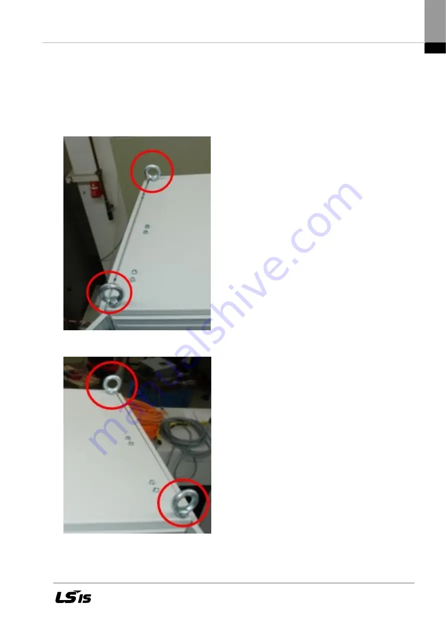
2.3.4  Removing the Transport Eyelets 

First remove the four transport eyelets on the control cabinet roof. 


Figure 2:  Transport eyelets, left 


Figure 3: 

Transport eyelets, right 


Summary of Contents for LSRP-T100LT

Page 1: ...LSPV Solar Inverter User Manual LSRP T100LT T160LT ...

Page 2: ...3 2 Ventilation Cooling 10 2 3 3 Tilting the Control Cabinet Roof 13 2 3 4 Removing the Transport Eyelets 13 2 3 5 Loosening the Bracket Bolts 14 2 3 6 Tilting the Roof 14 2 3 7 Tightening the Bracket Bolts 15 2 4 PV Generator Requirements 16 2 4 1 DC Connection to the Solar Inverter 16 2 4 2 Reverse Current Due to Module Defects 16 3 Description of the Unit 17 3 1 Control Terminal Strip Functions...

Page 3: ...and the Menu Language 31 5 4 Activating the Device 34 5 5 Navigation via the Operating Pad 35 5 6 Menu Structure 38 5 7 ENS Test 46 5 8 Password Entry 47 6 Troubleshooting 48 6 1 Self test error messages 48 6 2 Warnings 48 6 3 Faults 48 6 4 Fault Acknowledgement 49 6 5 List of Fault Messages 50 7 Maintenance 52 7 1 Maintenance Instructions 52 7 2 Maintenance Schedule 52 8 Technical data 54 9 Conta...

Page 4: ...hose responsible for safe operation of the unit When selling letting or otherwise passing on the device to third parties always enclose these safety notes WARNING Any misuse of this equipment failure to observe these safety notes or unqualified interference with the safety equipment or unit could result in damage bodily injury electric shock or even death 1 2 Explanations These safety notes use th...

Page 5: ...y by electric shock WARNING Large leakage current Make sure to connect to grounding before connecting to the power supply circuit WARNING Health risk for persons with cardiac pacemakers metallic implants or hearing aids in the immediate vicinity of electrical equipment CAUTION Surfaces of the housing can be hot Risk of injury Risk of burns CAUTION Risk of injury by improper handling Bodily injury ...

Page 6: ...ric circuits and devices according to the safety regulations and to mark them appropriately according to the work instructions Qualified personnel must be in possession of sufficient safety equipment and have first aid training Use only accessories and spare parts approved by the manufacturer The safety laws and regulations of the country in which the unit will be used must be observed The ambient...

Page 7: ...lectrical equipment Observe the general construction and safety regulations for working with heavy current installations Before switching on it must be checked that the power plug is firmly locked in place The PV generator may only be connected when it is completely de energized The operator must observe all of the above regulations at all times WARNING Photovoltaic systems have certain special ch...

Page 8: ...th metal implants or metal fragments or persons wearing hearing aids must consult their physicians before accessing such areas as a risk to their health must be assumed 1 7 Protection against Touching Hot Parts CAUTION Surfaces of the housing can be hot Risk of injury Risk of burns Do not touch parts of the housing that are close to heat sources Risk of burns Before accessing a unit leave it to co...

Page 9: ... on handling and assembly The weight of the LSPV inverter is 860 kg Use suitable assembly and transport equipment Take appropriate measures to prevent jamming and crushing Only ever use suitable tools Use special tools if specified Use lifting equipment and tools in the correct manner If necessary use suitable protective equipment for example safety goggles safety shoes safety gloves Do not stand ...

Page 10: ...ty notes Figure 1 View of the LSPV inverter control cabinet 2 1 Transport The LSPV inverter consists of a control cabinet in which all components required for its operation are housed The control cabinet has 4 transport eyelets attached to the roof Given the considerable weight of the LSPV inverter it is recommended to use a crane to load and unload it when transporting 2 2 Storage Store in a dry ...

Page 11: ...itable ventilation For cooling the unit requires an air flow rate of 2500m air hour maximum capacity at the output o The supplied air must not contain any aggressive or electrically conductive gases or gases that jeopardize system function o The doors must be closed during operation o The supplied air must be dust free In order to protect the interior space of the inverter against contamination fi...

Page 12: ...11 IP24 Housing Filter mat 1500 min 1000 max 200 Air duct Filter mat Filter mat ...

Page 13: ...12 Abutting Installation REFUSOL REFUSOL Air duct Spaced Installation REFUSOL REFUSOL Air duct Air duct ...

Page 14: ... cabinet components the roof of the cabinet must be tilted before the system is put into operation To do this proceed as follows 2 3 4 Removing the Transport Eyelets First remove the four transport eyelets on the control cabinet roof Figure 2 Transport eyelets left Figure 3 Transport eyelets right ...

Page 15: ...fastening bolts on the roof brackets at the top of the cabinet frame Figure 4 Right bracket bolts roof folded down Figure 5 Left bracket bolts roof folded down 2 3 6 Tilting the Roof After having loosened the roof bracket fastening bolts tilt the roof see figure 6 Figure 6 Tilted roof ...

Page 16: ...tening the Bracket Bolts Now tighten the bracket bolts firmly Figure 7 Right bracket bolts roof tilted up Figure 8 Left bracket bolts roof tilted up CAUTION Risk of injury Secure the roof against falling down again ...

Page 17: ...ge In order to prevent such damage to PV systems appropriate measures should be taken There are two different cases 1 The PV system is designed in a way that the reverse current flowing in an event of fault which in the worst case consists of the sum of the short circuit currents of all intact strings does not lead either to the destruction of the damaged string or to any secondary damage This dep...

Page 18: ...circuit Two indicator lamps in the cabinet door indicate when the PV generator is connected and the inverter is feeding into the mains The DC positive and negative line are internally connected to PE over an isolation measuring unit which triggers a fault in the case of a DC side ground connection The graphic display built into the cabinet door with an 8 key control pad lets you display various da...

Page 19: ...V10 4 Supply disconnection contactor Q11 5 Three phase transformer T10 6 Inverter T20 7 Contactor Q22 8 Contactor Q23 9 Overload protection F20 10 EMV DC Filter V20 11 Circuit breaker with motordrive Q20 12 Inverter controller T20 13 DC Voltage metering 14 Insulation measuring A21 15 Auxiliary supply 16 Overvoltage protection F15 ...

Page 20: ...ropriate waiting period and only when it has been verified that the system is completely de energized When working on the open unit keep in mind that some parts are still live The operator is responsible for all units to be installed and connected in accordance with the recognized technical regulations of the country it is installed in and other regional regulations Cable dimensions fuses groundin...

Page 21: ...20 4 2 Overview of the OPEN Control Cabinet Figure 10 Overview of the LSPV inverter connections ...

Page 22: ... DC current The DC current must never exceed 240 A under any circumstances otherwise the unit could be severely damaged 2 The specified line cross sections apply only to a specific laying system As a result the following must be checked in every individual case Line laying system Desired efficiency Maximum voltage load this can be taken from the technical data on the LSPV inverter Maximum current ...

Page 23: ...on order See Power connection 4 6 Auxiliary Power Supply This is connected to the terminal block X01 The auxiliary power supply 1AC 230 V 990 W and a pre fuse 10Agl must be provided by the operator X01 1 Life conductor L X01 2 Neutral conductor N X01 3 PE conductor The position of the terminal block is shown in Figure 10 A surge arrester is integrated into the control cabinet Note It is not recomm...

Page 24: ...t breakers Q20 and Q21 and isolates the PV generator from the LSPV inverter 4 8 DC Grounding The inverter side is not grounded The voltage system available TT net is not grounded thus allowing one sided DC grounding Note Some PV module manufacturers specify for certain modules the grounding of a DC plus or negative terminal The grounding must be connected at the plus or minus pole of the PV genera...

Page 25: ...will shut down automatically The display shows the following message ENS error A ground leak cannot be successfully detected through the DC grounding circuit breaker There is the possibility that during operation via power sharing through the DC cable from the grounded pole and earth nevertheless be released WARNING The insulation condition of the PV generator is tested at regular maintenance inte...

Page 26: ...MMC not supported X10 11 Operating pad connection X13 Ethernet X14 15 RS485 LEDs for status display RED Fault Yellow Operation Green Ready for activation Blue Ready for operation OR MMC plugged in LED blinking OR Communication with MMC LED blinking rapidly X17 Digital inputs outputs with LED for status display X18 Analog inputs outputs and signal relay Operating pad X19 Transducer input not suppor...

Page 27: ... Data bits 8 Protocol USS 4 6 words Address 0 Figure 12 Operating pad connection Ethernet interface for LS Web Server Terminal Designation Comment X13 Standard connection RJ45 plug isolated Note The Ethernet interface is protected against external overvoltages This is done directly on the adaptor of the surge protector F12 F12 is installed on the left control level of the control cabinet Please us...

Page 28: ... transmission of data e g to a data logger of a remote monitoring system Figure 13 Connection of the standard interface For operation of this interface ensure that the same interface configuration is set for every bus user Bus termination is made by means of wire bridges on X14 to the last bus user inverter n USB connection of operating interface Æ Service interface Terminal Designation Comment X1...

Page 29: ...ion Level according to EN61131 Type 2 SPS compatible Digital outputs can drive max 20 mA The line of LEDs indicate the status of the inputs outputs 1 P24V output Load capacity max 100 mA 2 Relay NO contact 3 Relay contact root 4 Relay NC contact Start insulation switching Load capacity AC DC 24V 10 1 5A Floating 5 Ground P24V Free 6 7 Difference analog input 1 Free Voltage input 10 10 V Resolution...

Page 30: ...e operator External signal Default setting X54 LSPV inverter function description Internal signal 1 24 V DC supply 2 3 Mains disconnection with Q10 24 VDC 3 A 4 0 V DC supply 5 24 V DC supply 6 Max 240 VAC 1 A 7 Main switch Q10 On 8 24 V DC supply 9 Enable solar generator 50 mA 10 Enable mains feed in 50 mA 11 Acknowledge inverter fault 50 mA Relay coil 12 Inverter fault message 24 VDC 100 mA ...

Page 31: ...e edited digit to the left digit to the right decade jump Select the menu ESC Acknowledge failures and delete entries Confirm the selected menu and entered data 4 12 Internal Data Logger The LSPV inverter features an internal data logger that allows measured values to be simultaneously recorded in the form of parameters The data logger is implemented as a ring buffer If this buffer is full the old...

Page 32: ...t the AC power switch on the LSPV to the ON position Note The control panel is only active with activated auxiliary supply voltage The control panel including its staus indicators display and operator keys is only active with activated auxiliary supply voltage because the electronics of the LSPV inverters is exclusively supplied from the auxiliary voltage 5 3 Setting the Country Code and the Menu ...

Page 33: ...the screen requesting you to set the country code You can select the country desired from the list The term country code as such is not displayed in the menu The display will be illuminated after you have pressed the first key 1 Use the and keys to select the country code which is specific for your country and your location When you select the country code you automatically select the menu languag...

Page 34: ...ot possible any longer If you wish to accept the country code press to confirm Changing the menu language The language selected does not affect the country code in any way Proceed as follows to change the menu language 1 Press F1 to open the menu 2 Use the and keys to select the forth menu item Configuration 3 Press to confirm 4 Use the and keys to select the first menu item Languages 5 Press to c...

Page 35: ...ng sequence of operations which you can follow on the display of the operating pad Self test Ö All status LEDs are lit for approx 6 seconds The initialization cycle starts Ö Ready status LED flashes Display Ö PAC Feed power in watts W Ö UAC Line voltage in volts V Ö UDC Solar cell voltage in volts V Ö State Initializing Figure 14 Initializing display Initializing has been completed Ö READY status ...

Page 36: ...ne voltage in volts V Ö UDC Solar cell voltage in volts V Ö E TAG Yield of the day in kWh Check time o If the electronic system has been disconnected from the supply voltage for a longer period approx 2 3 weeks incorrect time setting is possible For this reason it is necessary to check and if required to reset the time as follows before switching on o Press F1 key to open menu o Use arrow key to s...

Page 37: ...from menu lvel exit from input level without acknowledge Confirm the selected menu and entered data Basic screen display Figure 17 Operating mode display PAC Present feed power UAC Line voltage UDC Solar cell voltage in volts V E TAG Yield of the day in kWh Graphic display Press the arrow key once to display the course of the feed power of the day Figure 18 Feed power display Today Press the arrow...

Page 38: ...accrued so far Figure 20 Yield data display Standardized yield data display Press the arrow key then the arrow key to display the development of standardized yield data Figure 21 Standardized yield data display Press the ESC key to return to the basic screen Input for standardized data To obtain the standardized yield data press the F2 key and enter the connected PV generator power as follows ...

Page 39: ...d by 1 Figure 22 Standardized data input display Press the ESC key the previous normalized yield level will displayed Press the F1 key to display the menu Press the to apply the set value However this requires that the password is correct 5 6 Menu Structure The menu structure serves as a support to change to the individual information displays and setting displays Legend Legende Tasten des Bedienf...

Page 40: ... Menue Actual values DC AC Sensors F1 Menue DC power 6714 4 W DC voltage 504 2 V DC current 13 3 A F1 Menue Actual values DC AC Sensors F1 Menue AC power 6521 4 W AC voltage 228 2 V AC current 23 3 A AC frequency 50 0 F1 Menue Actual values DC AC Sensors F1 Menue Heat sink 40 4 C Interior 46 4 C Irradiation 622 3W qm Panel 37 4 C F1 Menue Analysis Actual values Failure memory Configuration Device ...

Page 41: ... USS address Protocol F1 Menue Configuration Communication Ethernet USS address Protocol IP address Subnet mask F1 Menue Configuration Communication USB Ethernet RS485 F1 Menue Configuration Communication Ethernet USS address Protocol IP address Subnet mask F1 Menue Protocol F1 Menue 1 Protocol F1 Menue 1 USS address F1 Menue 0 F1 ESC F1 ESC F1 ESC F1 ESC ESC F1 ESC F1 ESC F1 ESC F1 ESC F1 ESC F1 ...

Page 42: ...ress Subnet mask Standard gateway Protocol port F1 Menue Protocol port F1 Menue 21062 Configuration Communication USB Ethernet RS485 F1 Menue Configuration Communication RS485 USS address Protocol F1 Menue Configuration Communication RS485 USS address Protocol F1 Menue USS address F1 Menue 0 Protocol F1 Menue 1 F1 ESC F1 ESC F1 ESC F1 ESC ESC F1 ESC F1 ESC F1 ESC F1 ESC F1 ESC F1 Configuration Com...

Page 43: ...tion Send configuration Server IP Server Port Portal Testfunction F1 Menue Server IP F1 Menue 88 79 234 30 Configuration Portal settings Activation Send configuration Server IP Server Port Portal Testfunction F1 Menue Server Port F1 Menue 80 Configuration Portal settings Portal Testfunction Yes Testfunction F1 Menue Configuration Portal settings Activation Send configuration Server IP Server Port ...

Page 44: ...r F1 Menue F1 ESC F1 ESC F1 ESC ESC F1 ESC F1 ESC F1 ESC F1 Configuration Extended XModem Update Clear data logger Numerical list ENS Test F1 Menue ENS Test P0900 0 D0901 0 P0908 50 D0902 50 D0910 00 0 01 0 F1 Menue ENS Test D0910 00 0 01 0 D0903 00 0 D0903 01 0 P0909 11500 D0904 230 F1 Menue P0900 00 Start ENS Test F1 Menue 0 D0904 00 Test result of voltage test Volt F1 Menue 230 F1 ESC ESC F1 ES...

Page 45: ...erial number AXXXX F1 Menue F1 ESC ESC F1 ESC F1 ESC F1 Analysis Actual values Failure memory Configuration Device information F1 Menue Device information Version number Country Current language Device type Seriennummer F1 Menue Version number RFP 800R015 25 6 S F1 Menue Country Deutschland F1 Menue Device information Version number Country Current language Device type Seriennummer F1 Menue ESC F1...

Page 46: ...nput 0 or 1 0 RTP protocol 1 USS and RTP protocol Protocol port Input 1024 65535 default setting 21062 The port number is required for communication via Ethernet 3 Communication via RS485 USS address Input 1 31 This address is required for communicating with LSPV inverter via RS485 Note If you change this parameter address and wish to save it you must restart LSPV inverter The new address will onl...

Page 47: ...vice Carrying out the ENS Test Set P0900 to 1 Æ starts the ENS test P0901 shows the progress of the ENS test P0908 informs about the frequency ramp in mHz s P0902 shows the development of the simulated frequency P0910 00 shows the time measured until the lower frequency limit is reached P0910 01 shows the time measured until the upper frequency limit is reached Configuration Extended XModem Update...

Page 48: ...ltage value having caused turnoff at the lower limit P0905 01 shows the voltage value having caused turnoff at the upper limit ENS test status list 0 Initializing ready for start 1 3 Frequency test at the lower frequency limit 4 6 Frequency test at the upper frequency limit 7 9 Voltage test at the lower voltage limit 10 12 Voltage test at the upper voltage limit 13 ENS Test completed 5 8 Password ...

Page 49: ...line As opposed to the case with faults the warning is automatically acknowledged by the inverter and a new attempt is made to start up if the error no longer exists Warnings are signaled by a blinking red LED and are stored in the fault memory where they will remain even in the event of a power failure See the Faults section 6 3 Faults Permanently programmed and parameterizable limit values are c...

Page 50: ...ted the fault can be acknowledged as follows The signals Enable PV generator connection Enable mains feed in connection must be taken from the operator s terminal strip Then the fault acknowledgement must also be done over the operator s terminal strip NOTE to acknowledge a fault the signal status must change from 0 to 1 Once the signals Enable PV generator connection Enable mains feed in connecti...

Page 51: ...e notify the Service 060001 Wrong time The time is not set Please set time Control panel menu Configuration Date Time 070000 Update login No free resources for update Please restart the system and re update 070001 Update is running Another update already ongoing Please wait until completion of the update Then restart the system if necessary 080001 Wrong time Wrong time for data logger Please set t...

Page 52: ... detected Possibly caused by switching actions on the net 1 Wait until the situation has eased or remeasure the system frequency and line voltage 2 Contact the network operator if the line voltage fails to be within normal ranges 3 Contact the Service if the line voltage is within normal ranges 0A0013 PV isolation AFISR An isolation error was detected during the automatic system isolation test Ple...

Page 53: ...nd device fans for proper functioning and operational noise 12 months Check the thermostat settings door fan 12 months Visually check the fuses present 12 months Check the surge arresters on the AC and DC sides as well as the upstream fuses for outside damage 12 months Check the terminal connections of the power cables for tightness and retighten if necessary Look out for discolorations changes on...

Page 54: ...nce interval Check and if necessary replace the indicator lamps 12 months Check and if necessary replace the warnings labels 12 months Shorter maintenance intervals might be necessary depending on the location and ambient conditions ...

Page 55: ...pected verification by measurement Infeed from approx 500 W Internal consumption by night approx 50 W Internal overvoltage protection IEC 61643 21 EN 61643 22 type 1 2 Cooling ambient conditions EMC Cooling Controlled fan Ambient temperature 10 45 C Site altitude Up to 1000 m above sea level up to 2000 m with power derating Noise t b d Radio interference suppression EN55011 Group 1 Class A Certifi...

Page 56: ...55 Type LSPV inverter 100K Dimensions Width Height Depth 1200 mm 2000 mm 600 mm Weight 860 kg DC disconnection DC contactor AC disconnection Main switch and main contactor ...

Page 57: ...56 9 Contact You should have the following data at hand Exact description of the error and possibly HEX code of the error P0017 00 Data from the type plate ...

Page 58: ...57 10 Certificates The certificates are currently in preparation and will be made available for download from LSIS website www lsis biz when they are ready ...

Page 59: ...the following cases the service will be charged The failure occurred from the consumer s improper storage handling and careless handling The failure occurred from the consumer s error in the design of software or hardward The failure occurred from the error of power source and the defect of the connector The failure occurred from the force majeure fire flood gas disaster earthquake etc The product...

Page 60: ... IS Co Ltd Hanoi Vietnam Address Nguyen Khe Dong Anh Ha Noi Viet Nam Tel 84 4 882 0222 Fax 84 4 882 0220 e mail srjo lsisvina com LS VINA IS Co Ltd Hochiminh Vietnam Address 41 Nguyen Thi Minh Khai Str Yoco Bldg 4th Floor Hochiminh City Vietnam Tel 84 8 3822 7941 Fax 84 8 3822 7942 e mail sbpark lsisvina com LSIS Tokyo Office Tokyo Japan Address 16FL Higashi Kan Akasaka Twin Tower 17 22 2 chome Ak...

Reviews: