INTRODUCTION
Translation of the original instructions
8
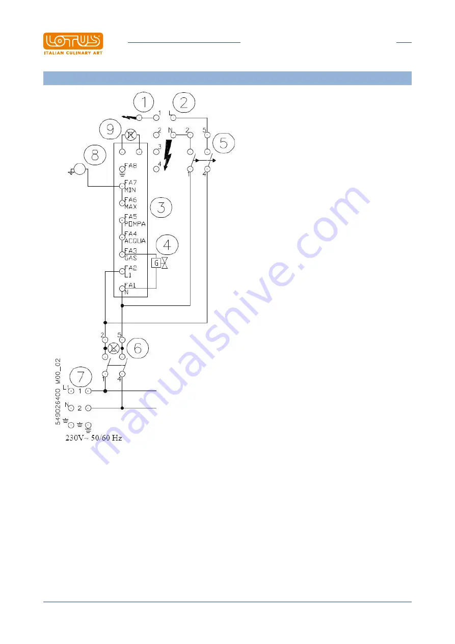
WIRING DIAGRAM CP-74G CP-76G
1 Ignition spark plug
2 Burner ignition control unit
3 Water level control unit
4 Gas solenoid
5 Power button
6 Bipolar switch
7 Power supply terminal board
8 Level probe
9 Red warning light


