background image

OPERATION 

Camera

(1) Connect the power adapter to the camera power input and ensure the 

camera is turned “ON”. Ensure the camera is set to channel 1.

Monitor

(1) Connect the supplied power adaptor to the power input of the monitor.
(2) Use the channel selection switch button and ensure the monitor is set 

to the same channel as the camera to view the picture. Note: If you 
experience transmission reception problems (eg. poor picture), you 
may need to select another channel on the camera and monitor 
and/or adjust the antennas on the monitor and camera to ensure they 
are pointing at each other.

(3) Adjust the volume to the desired level. You may also mute the audio 

option by pressing the mute button which is located at the front of the 
monitor.

(4) Adjust the brightness and contrast level as required

Try to position both the Camera and Monitor as high off the ground as

possible for better picture reception

NOTE 

ADDITIONAL CAMERA CONNECTION

This video security system allows you to view up to four different camera 
locations. Additional cameras are sold separately, please refer to  
www strategicvista.com for more information. 

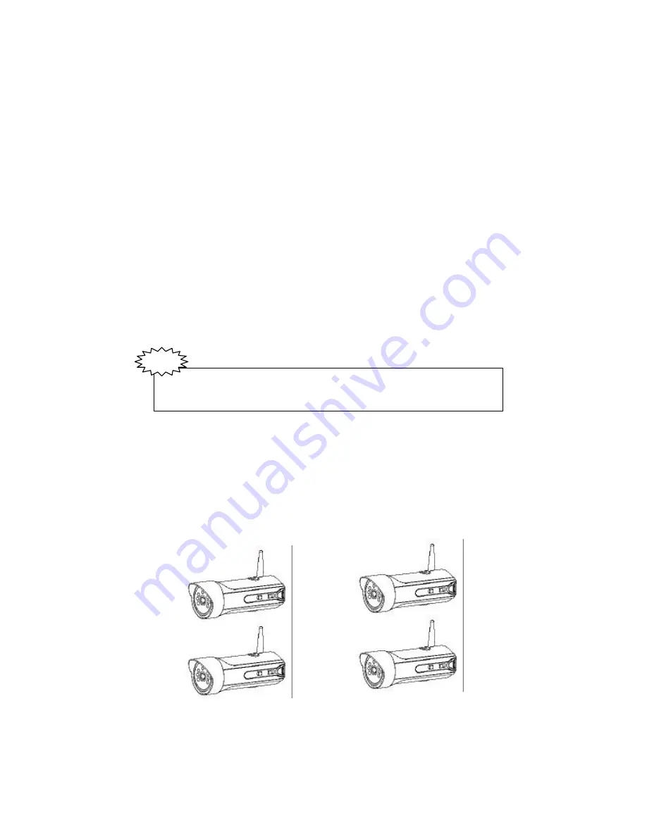
When connecting more than one camera to the monitor/camera system, 
you will need to set each camera to a different channel (Channels 1-4).  

CH 1

CH 3

CH 4

CH 2

6

Summary of Contents for SG4230

Page 1: ...ra FOR MORE INFORMATION WWW STRATEGICVISTA COM Before operating the system please read this manual thoroughly and retain it for future reference This product broadcasts over public airwaves and its vi...

Page 2: ...designed to provide reasonable protection against harmful interference in a residential installation This equipment generates uses and can radiate radio frequency energy and if not installed and used...

Page 3: ...power supply cord or plug is damaged b If liquid has been spilled or objects have fallen into the product c If the product has been exposed to rain or water d If the product does not operate normally...

Page 4: ...r Camera INSTALLATION Camera Monitor SYSTEM OPERATION Additional camera connection Auto Scanning Auto Manual Viewing Options Selectable Dwell Settings Connecting The Monitor To A VCR OPTIONAL ACCESSOR...

Page 5: ...stall and operate for your immediate security applications The RCA audio video outputs also allow you to connect a time lapse VCR or standard VCR for recording purposes To learn more about this 2 4GHz...

Page 6: ...GHz B W Monitor 1 2 4 GHz B W Wireless Camera with camera stand screws Owner s Manual Also includes 1 9V DC 500mA Adapter Camera 1 13 8V DC 1000mA Adapter Monitor 1 RCA Audio Video Cables Mounting ha...

Page 7: ...for the Auto mode sequences between cameras 1 4 b When the Manual mode is selected press the channel button to see each channel 6 Audio Mute Button Push this button to mute the sound on the monitor 7...

Page 8: ...h Controls power to the camera Note Please ensure that you set the switch to the OFF position before plugging the AC adapter into the unit 6 Battery Compartment Optional 4 AA batteries not included ca...

Page 9: ...rmly tighten the joint knob on the stand base 4 Connect the supplied 9V 500mA DC adapter to the DC IN jack at the rear of the camera and plug it into the electrical outlet MONITOR INSTALLATION DC INPU...

Page 10: ...mera to ensure they are pointing at each other 3 Adjust the volume to the desired level You may also mute the audio option by pressing the mute button which is located at the front of the monitor 4 Ad...

Page 11: ...e illuminated Auto Manual Viewing Options This system is preset to Manual mode with a dwell time of 2 seconds In Auto mode the LED light will be ON To manually view a specific camera location set the...

Page 12: ...e monitor to the Audio Video In of the VCR Please Note To record you must select the A V or AUX channel on your VCR Did You Know You have the option of connecting this system to a Time Lapse VCR A tim...

Page 13: ...properly check the following points Problems Causes and remedies Camera Monitor AC adapter not plugged in Power switch not turned on Monitor not turned on No power no picture sound AC adapter not plu...

Page 14: ...rronic Condenser 2 4 GHz 2 4835 GHz 4Ch FM 90dBu V 3m 1 0Vp p 75 Ohm Dipole 6 2 Length x 2 2 Diameter 4 AA batteries not included 14 to 122 F 10 C to 50 C 9V DC 500mA Adapter Screen Size 5 5 diagonal...

Page 15: ...temperature environment Extreme temperatures can shorten the life of the electronic devices Handle the monitor carefully Dropping it can cause serious damage to the unit Occasionally clean the unit w...

Reviews: