6
Electrical installation
6.2 电缆线和连线
24
6.1 Electrical Performance
The electrical characteristics are within ±3% of the indicated values of Isc, Voc and Pmax under STC (1000 W/m
2
Irradiance, a cell temperature of 25
℃
and an AM1.5 spectrum).
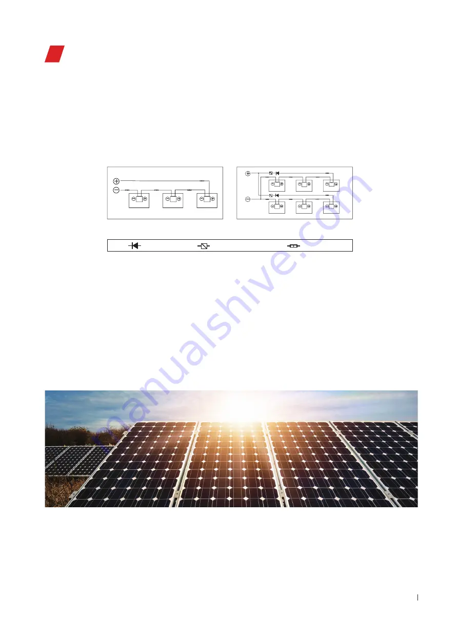
When modules are in series connection, the string voltage is sum of every individual module in one string. When modules
are in parallel connection, the current is sum of the individual module as shown in below figure 10. Modules with different
electric performance models can not be connected in one string.
Figure 10 Series Connection and Parallel Connection Circuit Diagram
The maximum allowed quantity of modules in string connection shall be calculated according to relative regulations. The open
circuit voltage value under the expected lowest temperature shall not exceed the maximum system voltage value allowed by
modules and other values required by DC electric parts. (LONGi modules maximum system voltage is DC1000V/DC1500V---ac-
tually system voltage is designed based on the selected module and inverter model.)
The correction value of VOC can be calculated by the following formula.
C
Voc
=1-βVoc×(25-T)
T: The expected lowest temperature of the installation site.
β: VOC temperature coefficient (% /
℃
) (Refer to module datasheet for further detail)
If there has reverse current exceeding the maximum fuse current flowing through the module, use overcurrent protection device
with the same specifications to protect the module. If quantity of parallel connection is more than 2, there must be an overcurrent
protection device on each string of module.
6.2 Cables and Wiring
P
V Modul
e's junction boxes with the IP67 protective level, can provide the safety protection for cable and wiring connection, also
for contact protection of non-insulating electric parts. Each module has two individual wires connecting the junction box, one is
negative pole and the other is positive pole. Two modules can be in series connection by inserting the positive pole at one end of
wire of one module into the negative pole of the adjoining module.
String Connection
Blocking Diode
Connector
Over Current Protection Device
Parallel Connection
According to local fire protection, building and electrical regulation, apply proper cable and connector; ensure the electrical and
mechanical property of the cables (the cables should be put in a catheter with anti-UV aging properties, and if exposed to air, the
cable itself should have anti-UV aging capability).
The installer can only use single-wire cable, ≥ 4mm2 (12 AWG), 90
℃
, with proper insulation capability to withstand the
maximum open circuit voltage (such as EN50618 approval). Need to select appropriate wire specifications to reduce voltage
drop.
LONGi requires that all wiring and electrical connections comply with the appropriate National Electrical Codes.
When cables are fixed on the bracket, avoid mechanical damaging cables or modules. Do not press cables by force. Adopt UV
resistant cable ties and clamps to fix cables on the bracket. Though cables are UV resistant and water proof, it is still necessary
to prevent cables from direct sun light and water immersion.
The minimum allowed bending radius of cables should be 43mm. (1.69 inch)


