background image


21 


Focus slider: Used to adjust focus. The focus slider represents the full focal range. 

Adjust focus by moving the slider in the desired direction.  


Z-stage speed: Used to adjust the speed at which the Z-stage moves with each 

action. For fine focusing at high magnifications, set the focus speed to Slow. When 
Step is selected, the Z-stage moves the distance of the selected objective’s depth of 
focus with each click.  


Z-position: Shows the position of the Z-stage and used to adjust focus. The focus 
position is expressed in mm along the Z-axis. Adjust focus by entering the desired 

value in the text box. 


Find focus: Used for instant autofocusing.  


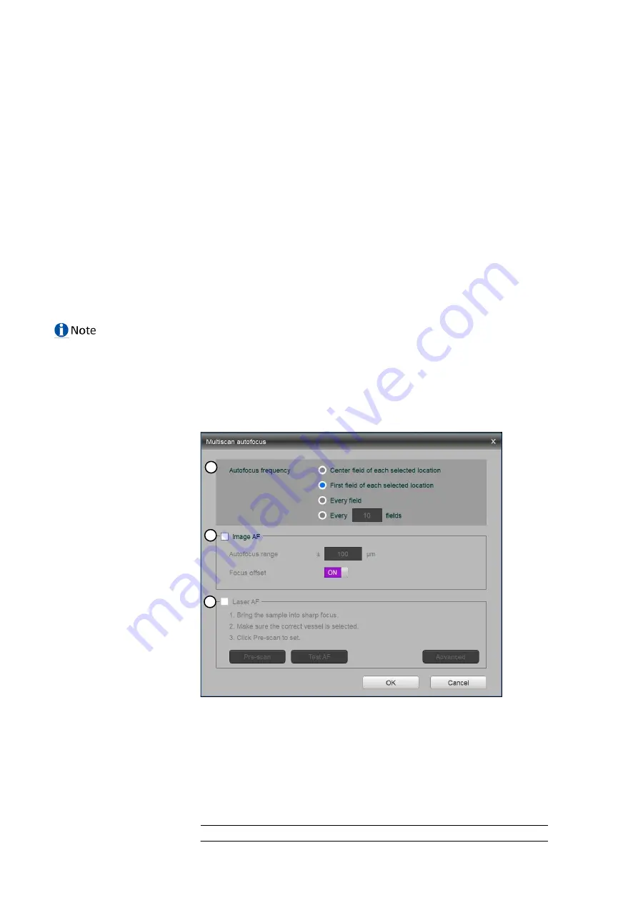
Multiscan AF: Used to set repeated autofocusing during an experiment.  

 
The CELENA®  X has two autofocus options: ‘Find Focus’ for instant autofocusing and 
‘Multiscan AF’ for repeated autofocusing during an experiment.  


Find Focus 
Find Focus is used to have the CELENA®  X find the optimal focal plane based on the image.  

 
Set the range to scan from the current focal position.  


A long search range is useful when finding the focal plane of an unknown object.  


A short search range is useful for fine focusing.  


The speed of the image-based autofocus is entirely dependent on the set exposure. Reducing 
the exposure will increase focusing speed. 


Multiscan AF 
Multiscan AF is used to set up autofocusing for demanding batch image acquisitions such as 
multi-well plate imaging, slide scanning, and time-lapse imaging.  
 
Prior to setting up Multiscan AF, make sure to bring the current field into sharp focus. The 
field must be focused sharply to setup subsequent autofocusing correctly. 


IMPORTANT!

  If using this feature, Multiscan AF must be set up for each channel used.  


Autofocus frequency: Used to set the autofocus frequency to use during an 

automated scan.  


Center field of each selected location 


First field of each selected location 


Every field 


Every _ fields 


Optimal AF frequency and range settings in Multiscan AF mode  


Optimal AF frequency 

Optimal AF range 

1


2


3


Summary of Contents for CELENA X

Page 1: ...3 USER MANUAL LBSM MD ML CLX 001 Rev 5 www logosbio com...

Page 2: ...vely be used to properly use the products described herein in accordance with the contractual terms for such product Copyright 2020 Aligned Genetics Inc DISCLAIMER The contents of this document are su...

Page 3: ...P 14 UNPACKING 15 CONNECTIONS 15 SHIPPING GUARD RESTRAINTS 15 TURN ON THE CELENA X 16 INSTALL FILTER CUBES AND OBJECTIVES 17 SHUT DOWN THE CELENA X 17 4 CELENA X EXPLORER 18 4 1 USER INTERFACE 18 CHAN...

Page 4: ...IMAGE QUALITY 48 EXPLORER 48 MECHANICAL 49 APPENDIX B SPECIFICATIONS 50 CELENA X HIGH CONTENT IMAGING SYSTEM 50 APPENDIX C ORDERING INFORMATION 51 INSTRUMENTS 51 OBJECTIVES 51 LED FILTER CUBES 51 ACC...

Page 5: ...hese safety notes and proceed with caution to avoid accidents personal injury damages to property This symbol and the word WARNING indicate a possible hazardous situation that if not avoided could cau...

Page 6: ...posure to beam Class 3b laser product Follow instructions for use Environmental symbol Symbol Description Waste Electrical and Electronic Equipment WEEE Do not dispose of this product as unsorted muni...

Page 7: ...on of the manufacturer Modification can result in electrical hazards or performance degradation The device is not suitable for use in the presence of a flammable anesthetics mixture with air or with o...

Page 8: ...ational laws and regulations for biosafety level requirements Read all user manuals thoroughly before using the instrument Keep all user manuals in a safe and accessible place for future reference Saf...

Page 9: ...se Optional Monitor Accessories Universal Vessel Holder Microplate Holder Single Slide Holder Power Cord Cable PS 1 Cable PS 2 Cable SIG Cable USB 2 0 Cable USB 3 0 Optional Cable Laser AF included wi...

Page 10: ...9 CELENA X Main unit CELENA X Controller Accessories Single Slide Holder Microplate Holder Universal Vessel Holder Cable PS 1...

Page 11: ...10 Cable PS 2 Cable SIG Cable USB 2 0 Cable USB 3 0 Optional Cable Laser AF Power cord...

Page 12: ...de scanning and well plate imaging CELENA X main unit CELENA X main unit Door Open the door to locate a vessel holder on the X Y stage and close it before operating CELENA X Explorer Condenser The ill...

Page 13: ...signals between the cameras and the computer USB 2 0 Transmit the communication signals between the main unit and the computer This device uses Class 3B near infrared laser and ultraviolet LEDs Make t...

Page 14: ...oftware CELENA X Explorer The CELENA X is controlled by the integrated CELENA X Explorer software CELENA X Explorer is pre installed to the computer supplied with the device CELENA X Explorer CELENA X...

Page 15: ...X Labels Top of the CELENA X Main unit Back of the CELENA X main unit Back of the CELENA X Controller 3 3 Setting up CELENA X Controller label CELENA X main unit label Laser safety label UV light saf...

Page 16: ...configuration of the computer supplied with the CELENA X i e erasing the hard drive to remove programs etc voids the product warranty CELENA X Controller Place the Controller near the CELENA X main un...

Page 17: ...ts must be removed before the CELENA X is turned on Store the screws in the accessories box for future use Make sure they are accessible in case you need to pack up for maintenance and servicing purpo...

Page 18: ...go to 5 2 Change filter cubes For detailed instructions on how to install objectives go to 5 3 Change objectives Make sure the installed filter cubes and objectives match what is set in the CHANNELS...

Page 19: ...wells and fields to capture Z STACK Allows you to capture multiple planes along the Z axis TIME LAPSE Allows you to set up time lapse sequences PROJECT Allows you to run load save and edit automated i...

Page 20: ...offset when adding channels Objectives This panel is used to select from the currently installed objectives The magnification and label on each objective reflects its profile which can be modified in...

Page 21: ...value in the text box Light intensity is controlled as a single parameter and expressed as a value between 1 1000 Filter cubes Represents the fluorescence channels available for imaging Up to four in...

Page 22: ...CELENA X find the optimal focal plane based on the image Set the range to scan from the current focal position A long search range is useful when finding the focal plane of an unknown object A short...

Page 23: ...ou define as the focal plane of interest and automatically calibrate the focus accordingly Laser AF Select to set up laser based autofocusing Make sure the current field is focused sharply and the cor...

Page 24: ...emission wavelength exceeding 750 nm LED filter cubes with an excitation wavelength less than 350 nm Vessel This section allows you to select the appropriate vessel area and fields to image Current ve...

Page 25: ...d Selected fields are filled in with yellow Select the acquisition order Click one of the following buttons to specify the order in which selected areas are to be captured Horizontal zigzag Horizontal...

Page 26: ...he Z stack This is automatically calculated Steps The number of planes to capture along the Z axis Interval The distance in m between each focal plane captured Time lapse This panel allows you to set...

Page 27: ...control panel is used to Create and run a project Open or save a project protocol Create project Allows you to start a project to image This creates a project folder where all generated data will be s...

Page 28: ...tion and or brightness contrast adjustment and are saved with a suffix of _modified in the filename Pseudocolor Shows the sample illuminated with the selected light source in pseudocolor Go to Setting...

Page 29: ...cts a color camera Bit depth Can select to capture images in 8 bit or 16 bit with the monochrome camera the actual bit depth of 16 bit images is 12 bit Saturated pixel color Can select to color satura...

Page 30: ...label them Filter cubes The filter cubes settings allows you to change filter cubes and set the pseudocolor and description for each installed filter cube See 5 2 Change filter cubes to learn how to...

Page 31: ...ws you to create a new vessel Create a vessel Select the vessel type Select the number of wells Select the well shape Input the vessel dimensions plate length A plate width B A1 row offset C A1 column...

Page 32: ...Add CHANNELS Repeat for all necessary channels Select areas and fields to be captured Optional Set up Z stack imaging Click Add Z STACK Optional Set up time lapse imaging Click Add TIME LAPSE Create...

Page 33: ...eful not to drop the vessel into the CELENA X when placing it on the vessel holder 2 Select an objective In the CHANNELS panel click the desired objective to select the corresponding magnification You...

Page 34: ...wn menu to control the condenser s iris diaphragm as desired For fluorescence imaging click the desired fluorescence channel to select the corresponding light source If the channel you need is not ava...

Page 35: ...l plane of an unknown object A short search range is useful for fine focusing The speed of the image based autofocus is entirely dependent on the set exposure Reducing the exposure 10 ms will increase...

Page 36: ...ystem defines as the optimal focal plane and what the user defines as the focal plane of interest and automatically calibrate the focus accordingly Laser AF Make sure the current field is focused shar...

Page 37: ...enter the desired value Range current Move the position to the desired start position To set the imaging range enter how far above and below the current position to set the imaging range Select Inter...

Page 38: ...and project has been created click RUN at the bottom of the PROJECT panel Make sure the CELENA X main unit door is closed for fluorescence imaging applications to block ambient light and improve fluor...

Page 39: ...tions If liquid is spilled on the instrument turn off the power and wipe dry immediately Do not exchange components between instruments unless they have been provided or authorized by Logos Biosystems...

Page 40: ...filter cube you want to change The filter cube stage will move to that position Unplug the connector A of the filter cube Loosen the screw B in the cube with a flat head screwdriver Gently pull out t...

Page 41: ...cubes list and click Double click the label box to change how it shows up in the CHANNELS panel Use the Color drop down menu to assign the filter cube a pseudocolor Use the DEL and buttons to edit the...

Page 42: ...41 Click Start Remove the vessel holder from the stage Click Next Click the objective you want to change The turret will turn to that position...

Page 43: ...t from the turret Replace it with the desired objective and screw it in securely If applicable set the correction collar A as needed Repeat as necessary Click Finish when complete This will return you...

Page 44: ...ws up in the CHANNELS panel If it is blank the label will be the name of the objective Use the DEL and buttons to edit the list of installed objectives as needed Click Apply 6 4 Adjust objective corre...

Page 45: ...44 Click Next Click the desired objective The turret will turn to that position Grasp the objective at its base and unscrew it from the turret Set the correction collar A as needed...

Page 46: ...45 Reinstall the objective with care Repeat as necessary Click Finish to complete A A...

Page 47: ...here the executable file exe is located and CELENA X_User db file in the User folder LogosBiosystems CELENA X CELENA X Exploer ini LogosBiosystems CELENA X Exploere CELENA X_User db You do not need to...

Page 48: ...plorer folder remains Logosbiosystems Logosbiosystems CELENA X Explorer If the Explorer folder exists delete the folder Install the new software Overwrite the backup files of CELENA X Explorer ini and...

Page 49: ...e iris diaphragm according to the objective and condenser used Increase light intensity Spots or blurs on image Clean the objective lens carefully and appropriately Make sure the vessel bottom is clea...

Page 50: ...changes in focus or stage position Turn on the light in the CHANNELS panel Inactive buttons Some of the buttons are contextual and only the controls relevant for the task at hand will be available In...

Page 51: ...d and the parfocal length of 60 mm are compatible Condenser Motorized basic or phase contrast condenser Basic 60 mm LWD condenser 4 positions Phase contrast 60 mm LWD condenser 4 positions with 3 phas...

Page 52: ...6 6 7 8 0 2 I10035 LUCPLFLN 40X 0 6 2 7 4 0 0 2 Fluorescence and phase contrast Cat Objective NA WD mm Correction mm I10038 UPLFLN 4XPH 0 13 17 I10039 UPLFLN 10X2PH 0 3 10 1 I10042 LUCPLFLN 20XPH 0 4...

Page 53: ...52 I10141 Cy5 Long Pass 620 60 665lp I10142 Custom Accessories Cat Product I10411 Microscope Calibration Slide 1...

Page 54: ...pecifications for a period of one 1 year Warranty Period from the date of purchase If the Device under this limited warranty fails during the Warranty Period the Company at its sole responsibility wil...

Page 55: ...85 Fax 82 31 360 4277 Email info logosbio com USA 7700 Little River Turnpike STE 207 Annandale VA 22003 USA Tel 1 703 622 4660 Tel 1 703 942 8867 Fax 1 571 266 3925 Email info usa logosbio com EUROPE...

Reviews: