Owner’s Manual (Hydraulic Flail Mower)
N14800 3 - August, 2004
2
Maintenance
General Service Continued:
5) Apply a thread-locking compound to the nut and
torque to 75 ft. lbs.
removal and assembly procedures if necessary.
Belt Removal:
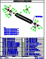
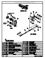
1) Refer to page 4-7 in Section 4 for an illustrated
parts listing.
2) Remove belt guard shield from left end of the
mower to expose the belt and its components.
3)
Unlock the 5/8” nuts on the threaded rod of
the belt tightener tube and thread them in to
relieve the spring tension on the belt.
4)
Remove the 1/2” nut and lock washer from the
1/2” bolt. Remove the bolt and pulley and the
two spacers.
5) Remove the belt.
6) Reverse the above steps for installation.
Pulley Removal:
1) Refer to page 4-7 in Section 4 for an illustrated
parts listing.
2) Remove the (2) screws from the taper lock
bushing of the rotor pulley.
3) Insert (1) screw into the threaded hole.
4)
Tighten screw until bushing grip is released. (If
excessively tight, lightly hammer face of pulley
using drift pin or sleeve).
NOTE:
Never hit
pulley directly with hammer.
5)
Replace the pulley by cleaning the shaft, bore of
bushing, outside of bushing and hub bore of all
oil, paint and dirt. File away any burrs.
6)
Insert bushing into hub. Match the hole pattern,
not threaded holes (each complete hole will be
threaded on one side only).
7) Apply a thread-locking compound to setscrews
and thread into the two opposing holes.
8) Position assembly on shaft and alternately torque
setscrews to 35 ft. lbs.
9) To increase gripping force, hammer face of
bushing using drift or sleeve. (Do not hit
bushing directly with hammer).
19) Re-torque screws after hammering.
11) Recheck screw torque after initial run-in, and
periodically thereafter, repeat steps 4, 5 & 6 if
loose.
12) Check alignment of the pulleys. Repeat pulley
CAUTION:
Excessive screw torque may
cause damage to the bushing
or sheave.
Rotor Removal
(Mower in Operating Position):
The belt and pulley should be removed with the
mower in operating position, but the procedures for
rotor removal and installation are greatly simplified
if the machine is turned upside down.
CAUTION:
If procedure is initiated with
mower in operating position,
proper lifting devices must
be used to lift and move rotor.
A mower rotor weighs
approximately 35 lbs./ft - i.e.,
a 90 inch mower rotor weighs
approximately 250 lbs.
Rotor Removal (Mower in Upside Down
Position):
This service section is written as if the mower is
upside down. If procedure is done with machine in
operating position, movable jacks will be needed to
support and move the rotor.
1)
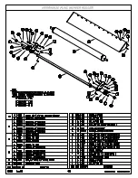
Refer to page 4-4 in Section 4 for an
illustrated parts listing.
2)
Attach a lifting device to both ends of
rotor, and apply a light tension.
3)
Loosen the set screws on the bearings.
4) Remove the (4) 1/2” nuts and lock
washers from the 1/2” bolts holding
the bearing to the anti-wrap plate on the
left hand side of the mower. Remove
the bearing. Remove the nuts and lock
washers on the (2) 1/2” bolts thru the
anti-wrap plate and the mower end
plate.
Summary of Contents for 48MH
Page 4: ......
Page 6: ......
Page 9: ...Section 1 Safety ...
Page 16: ......
Page 17: ...Section 2 Operating ...
Page 20: ......
Page 21: ...Section 3 Maintenance ...
Page 29: ...Section 4 Service Parts ...
Page 30: ......
Page 33: ......
Page 34: ......
Page 35: ......
Page 36: ......
Page 37: ......
Page 38: ......
Page 39: ......
Page 40: ......
Page 41: ......
Page 42: ......
Page 43: ......
Page 44: ......
Page 45: ......


