background image

26

Battle Ax OM

Parts Identification

Battle Ax 30 Series, Complete

Detailed parts breakdowns of the assemblies above (items) are listed on the following pages:
Item 1 - Belt Assembly (208066) - See page 36.
Item 2 - Motor Assembly, 6000PSI (208223)- See page 38.
Item 3 - Rotor Assembly, 41" with Planer (208054) - See page 32.
 

Rotor Assembly, 51" with Planer (208069) - See page 34.

Item 4 - Rotor Assembly, 41" with Hard Surface Planer (208310) - See page 32.
 

Rotor Assembly, 51" with Hard Surface Planer (208337) - See page 34.

Item 5 - Rotor Assembly, 41" with Double Carbide (208322) - See page 32.
 

Rotor Assembly, 51" with Double Carbide (208339) - See page 34.

Item 6 - Hook (Option) (208049) - See page 28.
Item 7 - Thumb Assembly (Option) (208105) - See page 43.

1

7 (Option)

5

4

3

6

(Option)

2

Summary of Contents for 41BX30

Page 1: ...Model Number Serial Number Date of Purchase 208186 Rev C 08 02 22 Battle Ax Excavator Mulching Head 30 Series 41 51 Owner s Manual and Parts Book Originating w Serial Number 101 136...

Page 2: ......

Page 3: ...LOFTNESS dealership or in any way so as in LOFTNESS judgment to affect its stability or reliability nor which has been subject to misuse negligence or accident nor to any machine or attachment which...

Page 4: ......

Page 5: ...on for pressure return case drain line ____ Verified recorded rotor RPM at full throttle per model chart in Loftness owner s manual RPM _____________ ____ Performed an Auxiliary system pressure stall...

Page 6: ......

Page 7: ...on for pressure return case drain line ____ Verified recorded rotor RPM at full throttle per model chart in Loftness owner s manual RPM _____________ ____ Performed an Auxiliary system pressure stall...

Page 8: ......

Page 9: ...s 6 Hydraulic Safety 7 California Proposition 65 Warning 7 Safety Decal Locations 8 Battle Ax Identification 10 Set up Instructions Hydraulic Connections 11 Mounting the Battle Ax to the Excavator 11...

Page 10: ...rdware and Manual Holder 30 Rotor Assembly 41 Battle Ax with Planer 208054 Rotor Assembly 41 Battle Ax with Hard Surface Planer 208310 Rotor Assembly 41 Battle Ax with Double Carbide 208322 32 Rotor A...

Page 11: ...cutter type two numbers motor system one letter sheave belt combo and one or two letters options An example for a Battle Ax 30 series of this type would be as shown below SIZE 41 41 cut 51 51 cut TYP...

Page 12: ...2 Battle Ax OM...

Page 13: ...codes regulations and or laws and in compliance with on product labeling and these instructions Make sure that all personnel have read this owner s manual and thoroughly understand safe and correct o...

Page 14: ...ustable Displacement Piston Motor 105cc Manually Adjustable Power Requirement 20 60 GPM up to 6000 PSI 45 150 hydraulic horsepower Optional Spade Hook Optional Pin Mount Quick Attach Mount or Flat Pla...

Page 15: ...afety hazard to eyes from hydraulic leaks and or flying debris USE OF PROTECTIVE EYEWEAR IS ABSOLUTELY MANDATORY for operator and others in the work area Due to the possible danger of flying debris it...

Page 16: ...ne to prevent falls Keep steps and platform cleared of mud and debris Always have an operator in the machine while the attachment is in operation Never leave the machine and attachment running and una...

Page 17: ...ent while the rotor is engaged or the engine is running entanglement could occur Operators are responsible to know the location and function of all guards and shields including but not limited to belt...

Page 18: ...place any worn torn hard to read or missing safety decals on your machine NOTE This section shows where safety related decals are applied on the machine For all machine decals see Machine Decals and S...

Page 19: ...No N28385 8 Part No N23506 WARNING SKIN PUNCTURE HAZARD HYDRAULIC LINES Protect hands and body from high pressure fluids N23506 1 Part No 4334 Safety Decal Locations Cont d 7 Part No 208824 5 Part No...

Page 20: ...r Cutting Teeth Drive Belt Cover Drive Belt Rotor Sheave Drive Sheave Manual QR Code Mounting Plate Hydraulic Thumb optional Hook optional Deflector Chains Shipping Stand Shipping Stand Hydraulic Moto...

Page 21: ...le Ax See below for hose requirements 1 Tank 16 Code 62 Split Flange 2 Pressure 16 Code 62 Split Flange 3 Case Drain 12FORB 4 Hydraulic Thumb if equipped 8FORB NOTE Route houses through ring 5 on fram...

Page 22: ...ting backward shut down the excavator Switch the TANK and PRESSURE connections Once connected restart the excavator engage the excavator auxiliary hydraulics and test for correct rotor rotation Refer...

Page 23: ...otor RPM on page 13 to increase or decrease the RPM If RPM adjustments are not necessary make sure power from the excavator is turned off then return the belt cover to its position securing with all b...

Page 24: ...DO NOT FORCE To DECREASE ROTOR RPM Loosen jam nuts 1 and 2 using a 19 mm offset box end wrench while holding the adjustment screw stationary with a 6mm Allen wrench Next hold jam nut 1 stationary whi...

Page 25: ...lp prevent the possibility of fire DANGER DO NOT allow ANY people or animals within 300 feet of the work area while operating this machine Operation WARNING Always stop engine and remove key before le...

Page 26: ...e Remove Shipping Stands on page 12 for reference Lower the Battle Ax to the ground Shut off engine and remove key Disconnect hydraulic hoses Detach excavator boom from the mounting bracket WARNING Do...

Page 27: ...ubrication instructions and schedules included in this section Maintenance Schedule H O U R S SERVICE POINTS SERVICE REQUIRED C H E C K C L E A N C H A N G E G R E A S E A D J U S T O I L Every 8 Mach...

Page 28: ...port plug after oil has drained out Using a funnel add hydraulic oil into the top port approximately 6 oz Maintenance Reinsert the plug back into the top port and tighten NOTE If replacing bearings o...

Page 29: ...4 and lift the cover off of the frame Front Motor Cover 2 7x 1 To remove the front motor cover 1 unscrew the seven bolts 2 and lift the cover off of the frame When maintenance repairs are complete ret...

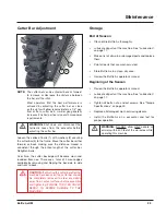
Page 30: ...ing the leading edge of the tooth while sharpening If the coloring in the tooth changes to either a blue or brown during the sharpening you have removed the temper and the tooth will not hold it s cut...

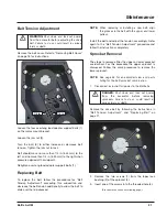
Page 31: ...ide over the top sprocket NOTE When replacing or installing a new belt align the grooves in the belt with the upper and lower pulleys Install the belt and adjust the tension accordingly Refer again to...

Page 32: ...after hammering 11 Recheck screw torque after initial run in and periodically thereafter repeat steps 4 5 6 if loose 12 Check alignment of the sprocket Repeat sprocket removal and assembly procedures...

Page 33: ...available by removing and flipping the bar side to side and front to back CAUTION If adjusting the cutter bar after the machine has been used the cutter bar should be completely removed to clear any...

Page 34: ...ity from striking rocks etc Consult factory Uneven cutting Teeth dull or worn excessively Replace teeth Engine RPM too slow Adjust machine RPM to full throttle Travel speed too fast Reduce travel spee...

Page 35: ...25 Battle Ax OM PARTS IDENTIFICATION Parts Identification...

Page 36: ...Assembly 41 with Planer 208054 See page 32 Rotor Assembly 51 with Planer 208069 See page 34 Item 4 Rotor Assembly 41 with Hard Surface Planer 208310 See page 32 Rotor Assembly 51 with Hard Surface Pla...

Page 37: ...1 208066 BELT ASSY 50 TOP 50 BOTTOM 37MM 2 1 208223 MOTOR ASM LINDE 105CC 132GPM 6000PSI HMR 57 3 1 208054 ROTOR ASSY PLANER 41 208069 51 4 1 208310 ROTOR ASSY HARD SURFACE PLANER 41 208337 51 5 1 208...

Page 38: ...28 Battle Ax OM Covers Skid Shoes Hook and Hitch Mount Parts Identification 1 3 1 2 16 1 15 14 13 10 Option 11 9 12 8 6 7 5 1 4 6 7...

Page 39: ...208047 SKID WITH BRACE 6 6 4055 NUT LOCK 5 8 TOP 7 6 4386 BOLT CARRIAGE 5 8 X 1 1 2 8 1 208048 PLATE SKID SHOE 9 1 208191 COVER BEARING DRIVEN END 10 1 208049 HOOK 30 SERIES OPTION 11 6 203587 WASHER...

Page 40: ...30 Battle Ax OM Cutter Bar Deflector Chains Motor Tension Hardware and Manual Holder Parts Identification 1 2 3 5 6 11 2 1 12 13 9 8 7 5 10 4 4 3...

Page 41: ...OCK 1 2 TOP 5 2 4375 PIN ROLL 3 16 X 1 6 45 202879 CHAIN 5 16 DEFLECTOR 9 LINK 41 55 202879 51 7 1 N49019 ROD CARBIDE 41 CHAIN 41 1 N49273 51 8 5 4494 BOLT 5 8 18 X 2 1 4 GR 8 41 6 4494 51 9 5 208800...

Page 42: ...r Assembly 41 Battle Ax with Planer 208054 Rotor Assembly 41 Battle Ax with Hard Surface Planer 208310 Rotor Assembly 41 Battle Ax with Double Carbide 208322 11a 11b 11c 12a 12b 12c 13 14 17 18 19 18...

Page 43: ...1 208323 ROTOR 41 WITH DOUBLE CARBIDE 12a 20 N49366 TOOTH BA PLANER INCLUDED ONLY WITH ITEM 11a 208055 12b 20 203014 TOOTH BA HARD SURFACE PLANER INCLUDED ONLY WITH ITEM 11b 208311 12c 20 N49090 TOOTH...

Page 44: ...Ax with Planer 208069 Rotor Assembly 51 Battle Ax with Hard Surface Planer 208337 Rotor Assembly 51 Battle Ax with Double Carbide 208339 11a 11b 11c 12a 12b 12c 13 14 17 18 19 18 15 16 7 6 3 2 1 10 9...

Page 45: ...H DOUBLE CARBIDE 12a 26 N49366 TOOTH BA PLANER INCLUDED ONLY WITH ITEM 11a 208070 12b 26 203014 TOOTH BA HARD SURFACE PLANER INCLUDED ONLY WITH ITEM 11b 208338 12c 26 N49090 TOOTH BA CARBIDE CARBIDE I...

Page 46: ...QTY PART DESCRIPTION 1 2 200286 SPROCKET 14MM 50 TOOTH X 37 2 1 N20805 BUSHING 1 1 2 TPL 3020 3 1 7121 03 KEY 3 8 X 2 4 1 208068 BELT POLY CHAIN 14MM 1750 X 37 5 1 N18975 BUSHING 2 3 16 TPL 3020 6 1...

Page 47: ...Lubrication QTY PART DESCRIPTION 1 2 N17007 GREASEZERK 1 8 NPT 2 2 4304 10 BULKHEAD FITTING GREASE HOSE 3 2 4304 HOSE GREASE 1 8 x 15 W FITTINGS 4 2 4472 ELBOW 1 8 90 DEG STREET Parts Identification...

Page 48: ...N20901 see page 40 For parts breakdown of item 7 Motor N49001 see page 41 For parts breakdown of item 27 Manifold 208237 see page 42 Parts Identification 16 2 1 5 3 4 6 7 22 24 23 25 26 21 18 19 20 1...

Page 49: ...1 208226 HOSE 1 X 32 5 16ORFS 16ORFS90 15 1 208210 ELBOW 45DEG 16MORFS 16 CODE 62 16 4 N20288 KIT SPLIT FLANGE SFXK 16 17 1 N11945 ELBOW 90 DEG 12MOR 12MJIC 18 1 N108213 ELBOW 90 DEG 12MJIC 22X1 5 19...

Page 50: ...PART DESCRIPTION 1 N28566 REBUILD KIT Includes Items 1 2 3 4 and 6 1 1 N28447 SEAL FRONT 2 2 N34130 CUP BEARING 3 2 N34131 CONE BEARING 4 1 N28448 SEAL REAR 5 1 N34132 RETAINING RING 6 1 N14159 GASKET...

Page 51: ...tle Ax OM Parts Identification Motor 105cc Adjustable Linde N49001 QTY PART DESCRIPTION 1 206841 KIT SEAL LINDE MOTOR Includes items 1 2 and 3 1 1 SHIM 56X72X1 2 1 205045 SEAL SHAFT LINDE 3 1 O RINGS...

Page 52: ...42 Battle Ax OM Manifold Check 132GPM 6000PSI 208237 QTY PART DESCRIPTION 1 2 N28281 PLUG 10MOR HOLLOW HEX 2 1 208239 CARTRIDGE CHECK Pressure Tank Pressure 1 1 2 Tank Parts Identification...

Page 53: ...T 3 8 X 1 SER FLG 2 3 4052 NUT LOCK 3 8 3 1 208111 PIN THUMB 4 1 208106 WELDMENT THUMB 5 2 N28010 DECAL GREASE GUN 8 6 1 N28577 DECAL VMLOGIX SMALL 7 2 207887 PIN THUMB 8 1 207740 CYLINDER 1 X 4 HYD 1...

Page 54: ...ine See Safety Decal Locations on page 8 Check and replace any worn torn hard to read or missing decals on your machine Part No N17013 Part No N28386 Part No N28385 Part No N23506 WARNING SKIN PUNCTUR...

Page 55: ...on Machine Decals and Signs Cont d Part No N28010 Part No N13721 Part No 209499 Part No 4138 Part No N13517 Part No N28576 Large Part No N49281 Small Part No N33105 Part No 203264 Part No 207851 CASE...

Page 56: ...46 Battle Ax OM...

Page 57: ...ustable Displacement Piston Motor 105cc Rotor Bearing 2 3 16 in Piloted Double Taper Rotor Tip Diameter 17 in 43 1 cm Sprockets Taperlock Belt 37 mm Synchronous Belt Mount Excavator Make Model Specifi...

Page 58: ...in 129 5 cm Overall Length B 63 8 in 162 0 cm 73 8 in 187 5 cm Overall Width C 27 7 in 70 4 cm 27 7 in 70 4 cm Overall Height D 38 3 in 97 3 cm 38 3 in 97 3 cm Number Of Teeth 20 26 Weight without mo...

Page 59: ...49 Battle Ax OM Appendix Torque Specifications Inches Hardware and Lock Nuts...

Page 60: ...50 Battle Ax OM Torque Specifications Cont d Metric Hardware and Lock Nuts Appendix...

Page 61: ......

Page 62: ...www loftness com Loftness Specialized Equipment Inc 650 So Main Street PO Box 337 Hector MN 55342 Tel 320 848 6266 Fax 320 848 6269 Toll Free 1 800 828 7624 Printed in USA Loftness 2022...

Reviews: