background image

101+ DELAYED EGRESS

MAGNETIC LOCKING SYSTEM

9

FORM 10111 Rev. C

04/11/2002

8

ON

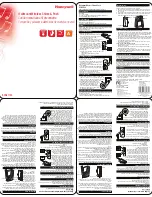
SW-4 DIPSWITCH SETTINGS 

OFF

7
6
5
4

3
2
3
2
3
2

1

DISABLED

DISABLED

DISABLED

DISABLED

DISABLED

30 SEC.

ENABLED

ENABLED

ENABLED

NUISANCE ALERT: 

Horn sounds when door pushed to alert people that door is armed. Avoids false alarms.

AUTOMATIC RELOCK: 

Door locks upon power up or after fire alarm. If set to OFF: manual reset required.

DOOR FORCED / DOOR PROPPED ALARM (SEC OPTION ONLY)

UNLOCK ALERT: 

Horn sounds whenever door is unlocked (and still has power applied to it).

ANTI-TAILGATE (SEC OPTION ONLY): 

When door closes it immediately relocks (cancels  time delay).

EGRESS DELAY TIME: 

This is the time that the door will remain locked and in alarm before it unlocks.

SWITCH #

ENABLED

ENABLED

15 SEC.

x
x

x

x
x

x

3
2

x
x

x

x

BY ON

-

BOARD ROCKER SWITCH ONLY

(

DEFAULT

)

BY ROCKER SWITCH OR AUXILIARY INPUT

BY ROCKER SWITCH AND AUXILIARY INPUT

DELAYED EGRESS DISABLED

CONFIGURE HOW

THE DELAYED

EGRESS EVENT IS TO

BE TRIGGERED,

USING DIPSWITCHES

2 & 3

SW-1

SW-1 TO RIGHT FOR N.O. OR NO CONNECTION: 

SW-1 TO LEFT FOR N.C.  CONNECTION: 

SW-1 FIRE ALARM INPUT: 

To configure interface to terminals 3&4
on main terminal block.

CONFIGURE FIRE ALARM INTERFACE DIPSWITCH (SW-1) FOR CORRECT TYPE OF INPUT.

A dry contact is required. It can be normally open or normally closed. If no direct connection is to be made, configure the input for normally open (SW-1 to RIGHT).

CONFIGURE THE SW-4 DIPSWITCHES TO SET THE FUNCTIONS OF THE SYSTEM.

Power should not be applied at this time. Note that dipswitches 4 and 6 are specifically for the SEC option. Also note that dipswitch 7 must be “on” for the lock to auto-
matically lock when powered up, or after a fire alarm condition. If it is off, the lock will remain unlocked, with the LED green, when power is applied. In order to lock it, a
reset input or valid code or TEK will be required after power up or after a fire alarm condition.

Summary of Contents for 101+

Page 1: ...01 DB Wiring Information 11 Monitoring Alarm DSM MBS Control Wiring 11 100CAB TR80 TR81 Hook up 12 Relock Time Delay 14 Nuisance Delay 14 Door Propped Delay SEC 14 Erasing Memory 14 Creating Master TEK Computer Programming 15 System 7 TouchEntry Key Programming 15 Keypad Initialization 15 Definition of Code TEK Functions Defaults 15 Keypad Manual Programming 16 TouchEntry Key Manual Programming 18...

Page 2: ...lications involving vertical rods or a mullion This unit has the same features as the 101 but one magnet houses a complete controller master unit while the other unit has a small interface board for connection to the master unit slave unit 101DB Delayed Egress magnet for double doors Two locks in one housing used in applications involving double doors without vertical rods or a mullion This unit h...

Page 3: ... screws may be necessary and the holes will have to be tapped Caution It is very important to make sure that magnet is secured to the structure of the opening It is the responsibility of the installer to provide structural reinforcement sufficient to ensure a safe installation Armature mounting hardware is for door thickness of 1 3 4 inches Sex nuts for thicker doors are available from your distri...

Page 4: ...holes Drill 2 1 4 dia holes per template for armature guide pins Armature mounting hole B is determined by the door type see below 1 PREP DOOR AND FRAME FOR STANDARD AND 101 2 UNITS The paper template is the preferable way to prepare the door and frame If for any reason it is not available use the dimensions shown below to mark the centerlines of the holes Note that the layout is not symmetrical w...

Page 5: ...terline of the armature The parting centerline of the doors should be used as the center of the door and frame prep HOLLOW METAL DOOR WOOD DOOR REINFORCED METAL DOOR 2 DRILL 1 2 DIA HOLE INTO SKIN OF DOOR ON SEX NUT SIDE ONLY DO NOT DRILL THROUGH DOOR 1 DRILL 11 32 DIA HOLE THROUGH DOOR DRILL AND TAP FOR 5 16 18 MACHINE SCREW HEX KEY STAR LOCKING WASHER TAPERED WASHER SEX NUT DRILL 1 2 DIA THRU HO...

Page 6: ...T be used for proper operation Use hex key to tighten the armature mounting bolt For solid core and hollow metal doors gently tap sex nut into posi tion with a rubber mallet before mounting armature assembly Proper use of hardware will allow armature to pivot slightly after securely tightening the mounting screw This is normal and necessary to allow armature to mate properly with magnet CAUTION Fa...

Page 7: ...w Drive in anti tamper plugs using a rubber mallet It is advisable to wait until the mag net is wired and tested before installing anti tamper plugs in case the magnet position must be adjusted NOTE For 101 2 see wiring information on page 11 to wire between units 8 FASTEN ELECTRONICS COVER AND LOCK GUARD After wiring and programming or if it is to be done later fasten the electronics cover s and ...

Page 8: ... features of the system See next page for setting dipswitches Note that they are numbered from 1 on the bottom to 8 on the top and Left is ON and right is OFF Main Terminal Block This terminal block has 18 screw terminals See page 10 for description of terminal functions and wiring information Access Control Terminal Block Used to interface Locknetics 3 wire cable keypad system 100CAB adapter cabl...

Page 9: ...IARY INPUT BY ROCKER SWITCH AND AUXILIARY INPUT DELAYED EGRESS DISABLED CONFIGURE HOW THE DELAYED EGRESS EVENT IS TO BE TRIGGERED USING DIPSWITCHES 2 3 SW 1 SW 1 TO RIGHT FOR N O OR NO CONNECTION SW 1 TO LEFT FOR N C CONNECTION SW 1 FIRE ALARM INPUT To configure interface to terminals 3 4 on main terminal block CONFIGURE FIRE ALARM INTERFACE DIPSWITCH SW 1 FOR CORRECT TYPE OF INPUT A dry contact i...

Page 10: ...gress cycle Apply a normally open dry contact to terminals 5 6 which closes when activated thereby shorting 5 to 6 The SW 4 dipswitches 2 3 will need to be set for proper operation See page 9 IMPORTANT DO NOT APPLY POWER TO TERMINALS 5 6 OR DAMAGE MAY RESULT ALARM OUTPUT Terminals 7 8 close when an alarm condition exists The following conditions will close the output delayed egress alarm condition...

Page 11: ... 101 2 model the flying leads provided for wiring between units can be extended as required Make sure that a good connection is made The anti tamper switch ATS option for the slave unit has flying leads whereas the ATS for the master unit is wired directly to the PC board and will sound the on board alarm On 101 DB units do not change or modify the factory installed wiring ...

Page 12: ...knetics 12 wire adapter cable does not work Only one 100CAB can be used Two keypads or TR83 TR84 readers can be plugged into a single 100CAB If the installation requires more distance between the two keypads readers an AUXCAB1 or AUXCAB16 can be used to extend the keypad reader cables If the installation involves TR80 or TR81 TouchEntry Key readers then the two readers must be wired in parallel 80...

Page 13: ...101 DELAYED EGRESS MAGNETIC LOCKING SYSTEM 13 FORM 10111 Rev C 04 11 2002 NOTES ...

Page 14: ...ause the LED to flash GREEN and the horn to beep C Press SW3 and the nuisance delay will be stored in non volatile memory NOTES 1 To program nuisance delay to zero eliminate Step B 2 Setting nuisance delay to zero will allow the lock to go into delayed egress the instant the door is pushed This may prove inconvenient in some applications DOOR PROPPED DELAY factory default 60 seconds The amount of ...

Page 15: ...has ended E Return SW4 1 to its original position if required NOTE Whenever new System 7 TEKs are entered the old ones are erased Also whenever computer programming is done or memory is erased all System 7 TEKs are erased KEYPAD 100CAB INITIALIZATION REQUIRED TO ENABLE KEYPAD TO FUNCTION It is necessary to initialize the keypad 100CAB any time that the memory is erased A Set SW4 dipswitch 1 to ON ...

Page 16: ...to end MORE CODES CAN BE DELETED BY RETURNING HERE TO DELETE CODES Master Code 5 Old Code to end MORE CODES CAN BE DELETED BY RETURNING HERE MANUAL PROGRAMMING KEYPAD When manually programming the 101 model lock using a keypad the keypad must first be initialized It is a recommended that the factory default Master Code be changed Doing so will delete all factory default codes and ensure the securi...

Page 17: ...its to end UP TO 150 NEW CODES CAN BE ADDED BY RETURNING HERE TO ADD ONE TIME ACCESS CODES Note that a three digit function code 113 sets the function of the user code Master Code 33 113 New Access Code 3 8 digits to end UP TO 150 NEW CODES CAN BE ADDED BY RETURNING HERE TO ADD SUPERVISED ACCESS CODES Note that a three digit function code 117 sets the function of the user code Master Code 33 117 N...

Page 18: ...communication plugs into ports and push each button in order Wait for LEDs to stop flashing before touching next key or pushing next button Waiting for longer than 7 seconds will terminate initialization E After the last key button is entered the audible will beep three times and the LEDs will flash indicating that programming has ended F Return SW4 dipswitch 1 to its original position TO DELETE T...

Page 19: ...nd UP TO 150 NEW TEKs CAN BE ADDED BY RETURNING HERE TO ADD ONE TIME ACCESS TEKs Note that a three digit function code 113 sets the function of the user TEK Master TEK 33 113 New PIN 3 8 digits New One time Access TEK to end UP TO 150 NEW TEKs CAN BE ADDED BY RETURNING HERE TO ADD ONE TIME ACCESS TEKs Note that a three digit function code 117 sets the function of the user TEK Master TEK 33 117 New...

Page 20: ...DURING NUISANCE ALERT STEADY YELLOW ON OPEN OPTIONAL SWITCH SELECTABLE FEATURES SEC SECURITY ALARM OPTION REQUIRED SW4 6 ON DOOR PROPPED OPEN ALARM DOOR IS HELD OPEN PAST RELOCK TIME FLASHING GREEN BEEPING CLOSED SW4 6 ON DOOR FORCED OPEN ALARM DOOR OPENED WITHOUT VALID RELEASE SIGNAL FLASHING RED BEEPING CLOSED PROGRAMMING INDICATIONS RELOCK DELAY PROGRAMMING ACTIVE FLASHING GREEN OFF OPEN DOOR P...

Page 21: ...is between lock and armature Armature magnet not installed properly p 5 6 DSM SEC option not working properly End Block on armature not aligned with DSM SEC switch s MAINTENANCE It is not recommended that the magnet be painted unless ordered with in iridite primer If the unit must be painted it is important that the mating surfaces of the magnet and armature not be painted The TouchEntry Key reade...

Page 22: ...101 DELAYED EGRESS MAGNETIC LOCKING SYSTEM 22 FORM 10111 Rev C 04 11 2002 OVERALL DIMENSIONS 101 101 2 101 DB ...

Reviews: