background image

12

4  

Domestic side piping


Installation & Operation Manual

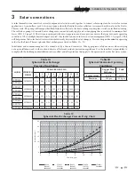
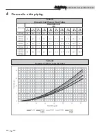
Table 4A

Recirculation Lance Pressure Drop Values

Flow Rate (gpm)

Pressure Drop (psi)

0.2

0.07

0.4

0.25

0.6

0.5

0.8

0.83

1

1.22

1.2

1.68

1.32

1.98

1.4

2.2

1.6

2.78

1.8

3.41

2

4.11

2.2

4.85

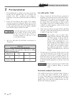
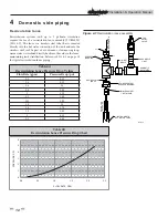
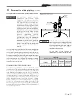
Recirculation lance

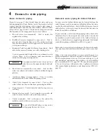
Recirculation systems with up to 2 gal/min circulation 
require the use of a recirculation lance assembly (TUB30000) 
(FIG. 4-1). The lance is a stainless steel tube that is inserted 
directly into the hot water connection of the tank and into the 
stainless steel coil. As part of a continuous, slow-moving loop, 
warm water is circulated directly back into the coil, via the lance, 
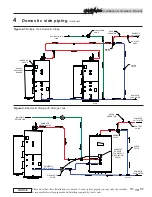
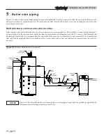
maintaining tank stratification. Reference FIG. 4-5 on page 18 
for typical recirculation lance piping.

T&P 

RELIEF 

VALVE

RECIRCULATION

LANCE

REDUCER

BUSHING

STAINLESS STEEL

REDUCER BUSHING

STAINLESS STEEL

1" NPT NIPPLE

1" NPT DOMESTIC 

HOT WATER TUBE

BRASS NIPPLE

1" NPT

1 1/2" NPT

NIPPLE

1/2" NPT

1" NPT

1 1/2" NPT

1 1/2" NPT

1 1/2" N

P

T

1 1/2" N

P

T

1 1/2" N

P

T

1" NPT

RE
CI

RCUL

A

TIO

N

WA
TE

R

 L

IN

E

DO
M

E

S

TIC


HO
T W

A

TE

R

DOMESTIC 

HOT WATER

IMG00013

Figure 4-1 Recirculation lance assembly

Table 4B

 Recirculation Lance Pressure Drop Chart

0

1

2

3

4

5

6

0.0

0.5

1.0

1.5

2.0

2.5

PRESSURE, PSI

FLOW RATE, GPM

Summary of Contents for Strato-Therm+ STU150

Page 1: ...sed by a qualified heating installer service technician Read all instructions before installing Perform steps in the order given Failure to comply could result in severe personal injury death or subst...

Page 2: ...ed to personal injury or property damage HAZARD DEFINITIONS 2 PLEASE READ BEFORE PROCEEDING 3 1 GENERAL INFORMATION Operating Restrictions 4 Tank Shipment 4 Components 4 6 Spherical Heat Exchanger 7 2...

Page 3: ...gas supplier from a neighbor s phone Follow the gas supplier s instructions If you cannot reach your gas supplier call the fire department WARNING NOTICE WARNING WARNING 3 The following chart details...

Page 4: ...ry if your specific application is not covered in this manual The tank is not intended for use in gravity water heating applications Table 1A Strato Therm Tank Component Materials Component Material T...

Page 5: ...300 STU257 30 34 1 2 98 83 225 14 5 2875 STU350 36 40 1 2 98 83 325 14 5 3775 STU423 36 40 1 2 115 97 400 16 0 4650 STU504 42 46 1 2 121 103 475 17 0 5475 STU650 48 52 1 2 131 111 625 20 0 7050 STU752...

Page 6: ...ger Outlet Blue Label Table 1D Tapping Measurements Model A in B in C in D in E in F in G in H in I in O in P in STU150 2 1 4 12 1 4 21 1 4 28 3 4 33 50 3 4 55 1 4 71 76 3 4 3 1 2 3 1 2 STU200 3 1 2 1...

Page 7: ...l heat exchanger w tank Table 1E Tank with Spherical Measurements Model Spherical Model A in B in STU150 SHX40000 44 1 2 28 STU200 SHX40000 48 1 4 32 STU257 SHX40001 50 1 4 34 STU350 SHX40001 56 1 4 4...

Page 8: ...led outdoors as it is certified as an indoor appliance and must also be kept vertical on a level surface 2 Table 1C on page 5 shows the weight of all the tanks filled with water Ensure that the locati...

Page 9: ...sioning must be carried out by a licensed contractor Take appropriate safety measures when carrying out any installation work on the roof and observe all relevant accident prevention regulations It is...

Page 10: ...URE GAUGE TYPICAL SOLAR PUMP STATION CONTROLLER PRESSURE RELIEF VALVE FILL AND FLUSH VALVE EXPANSION TANK TEMPERATURE GAUGE SPHERICAL HEAT EXCHANGER SOLAR SENSOR IMG00040 Installation Operation Manual...

Page 11: ...d to allow water to flow in only one direction preventing back flow g Drain required Used to drain the tank for inspection or servicing h Mixing valve required Used to mix hot water with cold water to...

Page 12: ...ainless steel coil As part of a continuous slow moving loop warm water is circulated directly back into the coil via the lance maintaining tank stratification Reference FIG 4 5 on page 18 for typical...

Page 13: ...building recirculation system is installed the return water is brought back to the storage tank so as not to disturb the stratification of the Strato Therm Anti scald mixing valves Anti scald valves u...

Page 14: ...2 8 3 10 7 13 3 14 7 STU200 STU257 STU350 0 1 0 7 1 8 3 2 5 0 7 1 9 5 12 2 15 1 16 7 STU423 0 1 0 8 2 0 3 6 5 6 7 9 10 6 13 6 16 9 18 7 STU504 0 1 0 8 2 1 3 7 5 8 8 2 11 0 14 2 17 7 19 5 STU650 STU75...

Page 15: ...elief valve must be certified by a nationally recognized testing laboratory that maintains periodic inspection of listed equipment or materials The equipment and materials must meet the requirements f...

Page 16: ...tly connected to a drain Refer to local codes subject to freezing WARNING Do not install any valve between the relief valve and its connection or on the relief valve discharge piping Improper placemen...

Page 17: ...cal codes NOTICE IMG00042 SHUTOFF VALVE DOMESTIC HOT WATER CHECK VALVE DOMESTIC COLD WATER RECIRCULATION LINE MIXING VALVE DRAIN CIRCULATION PUMP TEMPERATURE GAUGE SHOCK ARRESTOR BACKUP HEAT SOURCE LO...

Page 18: ...ired by local codes NOTICE Figure 4 6 Recirculation Piping Flow Over 2 gal min RECIRCULATION LINE CIRCULATION PUMP SHOCK ARRESTOR SHUTOFF VALVE MIXING VALVE TEMPERATURE GAUGE RECIRCULATION LANCE DOMES...

Page 19: ...ese illustrations are meant to show system piping concept only the installer is responsible for all equipment and detailing required by local codes NOTICE Figure 4 7 Multiple Tank Domestic Piping BUIL...

Page 20: ...r flow are more balanced throughout each tank To ensure even charging and discharging of each tank it is recommended that only tanks of the same size are placed in the same manifold It is recommended...

Page 21: ...CHECK VALVE Y STRAINER TYPICAL EXPANSION TANK FILL VALVE PRESSURE RELIEF VALVE AIR SEPARATOR TEMPERATURE GAUGE BACKUP HEAT SOURCE SENSOR Please note that these illustrations are meant to show system p...

Page 22: ...ter heater immediately Follow the draining instructions and replace the T P relief valve If the T P relief valve weeps periodically it may be due to thermal expansion Do not plug the T P relief valve...

Page 23: ...Installation of a Temperature Pressure T P relief valve is required Owner monthly maintenance to include Visually check valves pipes and fittings for leaks Call a qualified service technician to repa...

Page 24: ...gpm First Hour Rating gal hr STU150 16 1035 23 1516 15 997 STU200 19 1244 27 1774 18 1125 STU257 19 1365 27 1965 18 1250 STU350 19 1550 27 2223 18 1395 STU423 27 1690 36 2451 26 1600 STU504 28 1816 3...

Page 25: ...5 507 555 507 555 507 555 507 555 507 555 507 555 507 555 18 1080 537 411 537 411 537 411 537 411 537 411 537 411 537 411 537 411 537 411 19 1140 567 267 567 267 567 267 567 267 567 267 567 267 567 26...

Page 26: ...8 528 548 528 548 528 548 528 548 528 548 528 548 528 548 528 548 528 14 840 590 722 590 722 590 722 590 722 590 722 590 722 590 722 590 722 590 722 15 900 632 917 632 917 632 917 632 917 632 917 632...

Page 27: ...328 418 328 418 12 720 358 274 358 274 358 274 358 274 358 274 358 274 358 274 358 274 358 274 13 780 388 130 388 130 388 130 388 130 388 130 388 130 388 130 388 130 388 130 14 840 417 986 417 986 41...

Page 28: ...Revision Notes Revision A ECO C09107 initial release STU I O Rev A 10 11 Printed in U S A...

Reviews: