background image

16

PC Program Instructions

6

Parameters

Cascade

Each burner control in the Cascade must be given a unique
address.  This address can be changed by accessing parameter

4CC

.  The Leader (top) burner (to which the thermostat/zone

control, system sensor, and system pump (if controlled by the
boiler) are connected) must be set to address 0.  All the
Member burners must be given an address from 1 to 15.  The
range of this parameter is 0 to 15.  The default value is 0-1. 

Master controlled through ModBus (Demand conf)

If the boiler or cascade is to operate based on its own inputs,
this must be set to No.  The boiler can still be monitored
through ModBus with this parameter set to No.  If the boiler
or cascade is to receive commands from ModBus, then this
must be set to Yes.  The default setting is No.

Reload short time ModBus out of order

When the boiler or cascade is receiving commands from
ModBus, but using its own system supply and tank sensor
readings, the commands must be refreshed at least every 4
minutes by the building automation system.  This is a fixed
timeout.  If the boiler or cascade is receiving either the system
supply temperature or the tank temperature reading from the
building automation system, that information should be
refreshed more often.  This parameter determines how often
this refresh must occur before the boiler or cascade goes into
its stand-alone mode.  The time range for this parameter is 0
to 120 seconds.  The default value is 10 seconds.

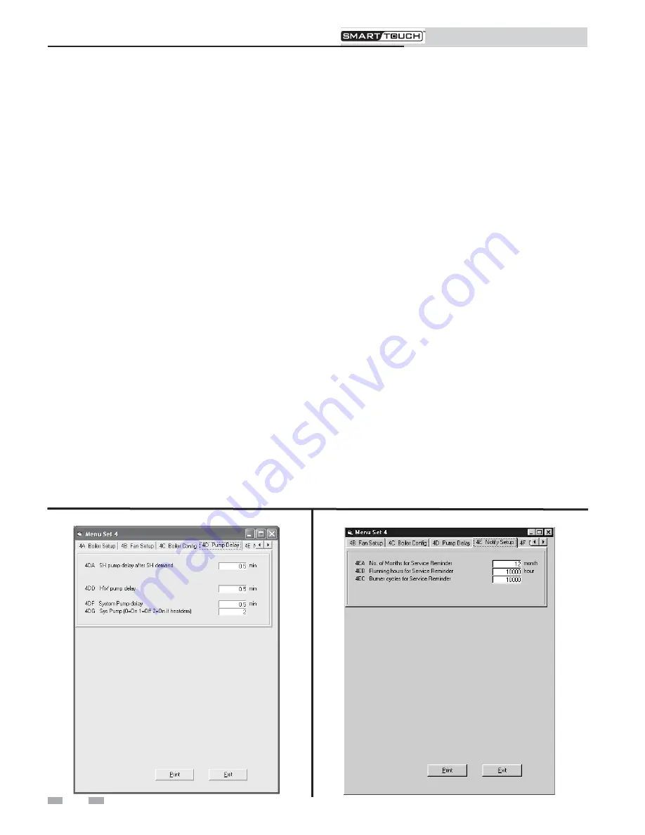
On the tabs at the top of the window, click on the tab labeled

4D Pump Delay

to set the delay time for the boiler, system,

and HW pumps (see FIG. 6-8 below).

Figure 6-8

Parameter Set 4D

SH pump delay after SH demand (Boiler Pump D)

This feature sets the length of time the boiler pump will run after
a SH demand has been satisfied. This parameter is adjustable by
accessing parameter 

4DA

.  The time range for this parameter is 0

minutes to 40 minutes.  The default time is 30 seconds.

HW pump delay (HW Pump D)

This feature sets the length of time that the HW pump (if
connected) will run after a HW demand has been satisfied. This
parameter is adjustable by accessing parameter 

4DB

. The time

range for this parameter is 0 minutes to 40 minutes. The default
time is 30 seconds.

System pump delay (Sys Pump D)

This feature sets the length of time the system pump (if
connected) will run after a SH demand has been satisfied. This
parameter is adjustable by accessing parameter 

4DC

. The time

range for this parameter is 0 minutes to 40 minutes. The default
time is 30 seconds.

To set the parameters for Service Notification, click on the tab
labeled 

4E Notify Setup

(see FIG. 6-9 below).

Sys Pump (Sys Pump mode)

The system pump can be set to operate different ways.  The
operating mode can be adjusted by accessing parameter 

4DG

.

When set to 0, the system pump will run continuously.  When
set to 1, the system pump output will not activate.  When set to
2, the system pump will turn on and off based on the space
heating call for heat.  The system pump will always turn off
when the Outdoor Air Shutdown feature is active.  The system
pump will always turn on when the freeze protection feature is
active.  The default setting is 2.

Figure 6-9

Parameter Set 4E

Summary of Contents for SMART TOUCH

Page 1: ...SYNC Installation and Operation Manual and the SYNC Service Manual before installing Perform steps in the order given Failure to comply could result in severe personal injury death or substantial pro...

Page 2: ...3 PC to Unit Connection 3 Starting the Program 4 6 2 Status Screen 5 6 3 Graphics Screen 7 4 Fault History Screen 8 5 Cascade Screen 9 6 PARAMETERS Parameter Information Screens 10 Changeable Paramet...

Page 3: ...r assigned to the USB cable above The programs display temperatures in F If you wish to display temperatures in C click on the Settings tab along the top of the Main Screen window and move the cursor...

Page 4: ...the upper left hand corner of the window A window opens in which you can type in the password see FIG 1 3 Note that the password is case sensitive and is in all CAPS Click on the Ok button or press th...

Page 5: ...o run at low fire Finally the 0 10Vdc input Voltage and Flame Current are shown To the right of the sensor temperature readings are the various setpoints The SH setpoint is the setpoint the SMART TOUC...

Page 6: ...active limits if any the last active limit the burner status the last fault and the date and time as stored in the SMART TOUCH PC Program Instructions While in the SMART TOUCH Status Screen you can g...

Page 7: ...he desired scale The top number represents F and the bottom number represents C Press the Ok button to close the Options window The background color of the Graphics Screen can be changed by pressing t...

Page 8: ...is shown as well as the number of successful and failed ignition attempts Finally a count of internal checks is shown The total number of occurrences of certain faults are also stored in the control a...

Page 9: ...t is a check box indicating if the temperature regulation is being held constant and if the Ramp Delay feature is active The Freeze P1 regulation box is checked when the next controller can be started...

Page 10: ...an adjustment to a parameter select the parameter to be changed from the appropriate set Click on the box next to the parameter and type in the value for the parameter Once an adjustment has been mad...

Page 11: ...stable The time range for each ramp delay is adjustable from 1 minute to 40 minutes with the total of all 6 ramp delays not to exceed 109 minutes The default delay time for Periods 1 2 and 3 is 2 minu...

Page 12: ...switching boiler on Parameter 2DJ is the minimum time delay between starting one burner and starting the next burner in the Cascade The range for this parameter is 0 seconds to 255 seconds The default...

Page 13: ...mperature setpoint for fixed operation or the maximum temperature setpoint when the outdoor air sensor is used This parameter can be changed by accessing parameter 4AA The temperature range of this pa...

Page 14: ...alue is 0 This feature will be active if this parameter is set to anything other than 0 Night setback temperature NSB Setp Once the internal clock has been set correctly the night setback feature can...

Page 15: ...has occurred or the maximum user setpoint has been reached Once the SH demand has been satisfied the setpoint will revert back to its calculated setting The boost temperature can be changed by accessi...

Page 16: ...ndow click on the tab labeled 4D Pump Delay to set the delay time for the boiler system and HW pumps see FIG 6 8 below Figure 6 8 Parameter Set 4D SH pump delay after SH demand Boiler Pump D This feat...

Page 17: ...re rises to or above this point the water temperature will be at its minimum setpoint This parameter can be changed by accessing parameter 4FD The temperature range of this parameter is 30 F 34 C to 9...

Page 18: ...eter 4GD The voltage range for this parameter is 0Vdc to 4GC The default value is 10Vdc Min BMS voltage to start demand BMS V Heat If parameter 4GK is set to 1 then the heat demand will be generated b...

Page 19: ...pear confirming that the file was saved Note that the new file name appears in the lower right hand corner of the SMART TOUCH PC program window BMS Voltage at min power BMS V min mod If parameter 4CB...

Page 20: ...Revision Notes Revision A initial release SYNC PCP Rev A Printed in the USA 4 10...

Reviews: