background image

24 

www.   lochinvar  .com 

    100221773_2000189439_Rev. 01   

Note:

 The purpose of a temperature-pressure relief valve 

is  to  prevent  excessive  temperatures  and  pressures  in 
the storage tank. The T&P valve is not intended for the 
constant  relief  of  thermal  expansion. A  properly  sized 
thermal  expansion  tank  must  be  installed  on  all  closed 
systems to control thermal expansion, see “Closed Water 
Systems” and “Thermal Expansion” section.

 Temperature-Pressure Relief Valve and Pipe 
Insulation

The T&P valve installed on this water heater is covered by 
insulation to minimize heat loss. The insulation has a hole 
on the bottom side to accommodate the valve outlet and 
allow for the piping connection. Do not restrict the outlet 
opening of the T&P valve.

T&P Relief Valve

T&P Relief Valve
Drain Line

Manual Relief Lever

T&P Relief Valve Insulation
(Outlet opening on underside)

Figure 25. 

Locate the temperature and pressure relief valve on the 
water  heater  (also  known  as  a  T&P  relief  valve).  See 
Figure 25.
1.  Locate  the  slit  running  the  length  of  the  T&P  relief 

valve insulation.

2.  Spread the slit open and fit the insulation over the T&P 

relief valve. See Figure 25. Apply gentle pressure to 
the insulation to ensure that it is fully seated on the T&P 
Relief Valve. Once seated, secure the insulation with 
duct tape, electrical tape, or equivalent. 

Important: 

The insulation and tape must not block the discharge 
opening or hinder access to the manual relief lever 
(Figure 25). Ensure a discharge pipe is installed into 
the T&P valve discharge opening per the instructions 
in this manual.

3.  Locate the hot water (outlet) & cold water (inlet) pipes 

to the water heater.

4.  Locate the slit running the length of a section of pipe 

insulation.

5.  Spread the slit open and slip the insulation over the 

cold water (inlet) pipe. Apply gentle pressure along 
the  length  of  the  insulation  to  ensure  that  it  is  fully 
seated around the pipe. Also, ensure that the base 
of the insulation is flush with the water heater. Once 
seated, secure the insulation with duct tape, electrical 
tape, or equivalent.

6.  Repeat steps 5 and 6 for the hot water (outlet) pipe.
7.  Add additional sections of pipe insulation as needed.

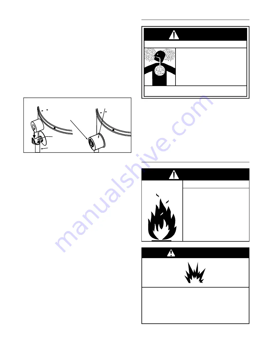
 HIGH ALTITUDE INSTALLATION


Breathing carbon monoxide can cause brain damage or death.

Always read and understand instruction manual.

 For operation above 10,100 ft. 

a high altitude orifice must be 
installed.

 Contact a qualified installer or 

service agency.

Breathing Hazard - Carbon Monoxide Gas

WARNING

This  heater  is  approved  for  operation  up  to   10,100  ft.  
without alteration.

Failure  to  replace  standard  orifice  with  a  high  altitude 
orifice  when  installed  above   10,100  ft.   could  result  in 
improper  and  inefficient  operation  of  the  appliance, 
producing carbon monoxide gas in excess of safe limits, 
which  could  result  in  serious  injury  or  death.  Contact 
your gas supplier for any specific changes which may be 
required in your area.

  GAS PIPING

• 

Do not use water heater with 

any gas other than the gas 
shown on the rating plate.

• 

Excessive pressure to gas 

control valve can cause serious 
injury or death.

• 

Turn off gas lines during 

installation.

• 

Contact qualified installer or 

service agency.

Fire and Explosion Hazard

WARNING

Explosion Hazard

Have a qualified technician make sure that the L.P. 
gas operating pressure does not exceed 14" water 
column.
Failure to do so can result in death, explosion, or 
fire.

WARNING

Summary of Contents for CVL075075

Page 1: ...truction manual must remain with water heater WARNING NOT FOR USE IN MANUFACTURED MOBILE HOMES MODELS PVN PVL 07575 and CVN075075 CVL075075 SERIES 210 211 300 Maddox Simpson Parkway Lebanon TN 37090 Phone 615 889 8900 Fax 615 547 1000 Technical Services email 2tech lochinvar com www lochinvar com Do not store or use gasoline or other flam mable vapors and liquids in the vicinity of this or any oth...

Page 2: ...valve discharge pipe requirements Temperature Pressure Relief Valve and Pipe Insulation High Altitude Installation 24 Gas Piping 24 Sediment Traps 25 Filling The Water Heater 26 Venting 26 Termination Clearances Sidewall Power Vent 27 Blower Assembly Installation 28 Installation Of Vent System 28 Planning The Vent System 28 Polypropylene Vent Systems 29 Condensate 29 Exhaust Venting 29 Important N...

Page 3: ...oid the risk of injury This product is certified to comply with a maximum weighted average of 0 25 lead content as required in some areas IMPORTANT DEFINITIONS Qualified Installer A qualified installer must have ability equivalent to a licensed tradesman in the fields of plumbing air supply venting and gas supply including a thorough understanding of the requirements of the National Fuel Gas Code ...

Page 4: ...e at highest risk of scald injury Feel water before bathing or showering Temperature limiting valves are available Read instruction manual for safe temperature setting BURN HOT HOT DANGER Overheated water can cause water tank explosion Properly sized temperature and pressure relief valve must be installed in opening provided Explosion Hazard WARNING Read instruction manual before installing using ...

Page 5: ... WARNING Breathing carbon monoxide can cause brain damage or death Always read and understand instruction manual Install vent system in accordance with codes Do not operate water heater if flood damaged For operation above 10 100 a high altitude orifice must be installed Do not operate if soot buildup is present Do not obstruct water heater air intake with insulating jacket or blanket Do not obstr...

Page 6: ...AND OR PROPERTY DAMAGE This manual contains instructions for installation operation and maintenance of the gas fired water heater It also contains warnings throughout the manual that you must read and be aware of All warnings and instructions are essential to proper operation of the water heater and your safety Since we cannot put everything on the first few pages READ ENTIRE MANUAL BEFORE ATTEMPT...

Page 7: ...nimum height of eight 8 feet above grade directly in line with the exhaust vent terminal for the horizontally vented gas fueled heating appliance or equipment The sign shall read in print size no less than one half 1 2 inch in size GAS VENT DIRECTLY BELOW KEEP CLEAR OF ALL OBSTRUCTIONS INSPECTION The state or local gas inspector of the side wall horizontally vented gas fueled equipment shall not a...

Page 8: ...OT WATER OUT MASSACHUSETTS INSTALLATION REQUIREMENTS 1 CONNECT ELECTRONICALLY CONTROLLED TIMER TO AN ALL BRONZE PUMP PUMP MUST ACTIVATE EVERY 6 HOURS FOR 60 SECONDS TURN PUMP TIMER OFF BEFORE CLOSING PIPING LOOP SHUT OFF VALVE 2 ALL WATER PIPING MUST BE INSTALLED AND INSULATED IN ACCORDANCE WITH MASSACHUSETTS CODE 248 CMR 780 CMR 3 PIPING LOOP BETWEEN WATER HEATER AND AIR HANDLER MUST BE INSTALLED...

Page 9: ...n 24 Main Manual Gas Shut off Valve 25 Gas Supply 26 Baffle Assembly 27 Rating Plate 28 Blower with Power Cord see Figure 6 29 Rubber Coupling see Figure 6 30 Inlet Water Shut off Valve 31 Union water connection 32 Hot Water Outlet Nipple 33 Anode under cap 34 Air Inlet Snorkel 35 Flue Collector 36 Thermal Expansion Tank required for all closed systems 37 Aluminum Burner see Figure 3 38 Gas Orific...

Page 10: ...Side Taps Caution harness has 120 VAC In operation See Planning The Vent System Condensate and Blower Assembly Installation for more information REPLACEMENT PARTS AND DELIMING PRODUCTS Replacement parts and recommended delimer may be ordered through authorized servicers or distributors When ordering parts provide complete model and serial numbers see rating plate quantity and name of part desired ...

Page 11: ...E SHALL BE PIPED DIRECTLY TO THE DRAIN OR EXTERNAL TO THE BUILDING MASSACHUSETTS INSTALL A VACUUM RELIEF IN COLD WATER LINE PER SECTION 19 MGL 142 Figure 8 This appliance has been design certified as complying with American National Standard CSA Standard for water heaters and certain models with side plumbing connections are considered suitable for Water Potable Heating and Space Heating Note Do n...

Page 12: ...be installed at water heater see Figure 8 Figure 9 or at hot water taps to further reduce system water temperature Mixing valves are available at plumbing supply stores Consult a Qualified Installer or Service Agency Follow mixing valve manufacturer s instructions for installation of the valves Before changing the factory setting on the thermostat read the Operating The Temperature Control System ...

Page 13: ...lways reference the wiring diagram for the correct electrical connections After making all electrical connections completely fill the tank with water and check all connections for leaks Open the nearest hot water faucet and let it run for 3 minutes to purge the water lines of air and sediment and to ensure complete filling of the tank The electrical power may then be turned on Verify proper operat...

Page 14: ...When using a gas fired water heater there is a risk of flammable vapors entering the combustion chamber being ignited by the burner flame and causing a flashback In order to detect such flammable vapors before they enter the combustion chamber this water heater is equipped with a flammable vapor sensor FVS It is a chemical absorption based sensor that is connected to the gas control thermostat see...

Page 15: ...han any point on the water heater s outer jacket and must be piped to an adequate drain The pan must have a maximum depth of 1 75 in Water heater life depends upon water quality water pressure and the environment in which the water heater is installed Water heaters are sometimes installed in locations where leakage may result in property damage even with the use of a metal drain pan piped to a dra...

Page 16: ...appliance by at least 3 in in every direction or if the appliance is installed in an alcove or closet the entire floor must be covered by the panel Failure to heed this warning may result in a fire hazard Clearance for servicing Adequate clearance of 24 in for servicing this appliance should be considered before installation such as changing the anodes etc Aminimum clearance of 5 5 in must be allo...

Page 17: ...t Gas and carbcn monoxide detectors are available Install water heater in accordance with the instruction manual and NFPA54 Breathing Hazard Carbon Monoxide Gas WARNING AIR REQUIREMENTS For safe operation an adequate supply of fresh uncontaminated air for combustion dilution and ventilation must be provided Note Contaminated or dusty air may cause build up on the blower wheel resulting in nuisance...

Page 18: ...or the purpose of vent installation See Installation Of Vent System section for complete venting installation instructions Chemical vapor corrosion of the flue blower assembly and vent system may occur if the air supply contains certain chemical vapors Spray can propellants cleaning solvents refrigerator and air conditioner refrigerants swimming pool chemicals calcium and sodium chloride water sof...

Page 19: ...n and free area is not known it may be assumed that wood louvers will be 20 25 percent free area and metal louvers and grilles will have 60 75 percent free area Louvers and grilles shall be fixed in the open position or interlocked with the equipment so that they are opened automatically during equipment operation 7 Special Conditions Created by Mechanical Exhausting or Fireplaces operation of exh...

Page 20: ...ng The Temperature Control System section in this manual This water heater should not be connected to any heating systems or components previously used with a non potable water heating appliance All piping components connected to this unit for space heating applications should be suitable for use with potable water Toxic chemicals such as those used for boiler treatment shall not be introduced int...

Page 21: ...requires a back flow preventer in the cold water line an expansion tank of adequate size must be installed 8 Combo Heating Systems require higher water temperatures than other applications When the system is used to supply water for Combo Heating applications a means such as mixing valve must be installed to temper the water in order to reduce scald hazard potential see Figure 22 Figure 23 Install...

Page 22: ...perature pressure relief valve operation water discharged from the valve due to excessive pressure build up The temperature pressure relief valve is not intended for the constant relief of thermal expansion This condition is not covered under the limited warranty A properly sized thermal expansion tank should be installed on all closed systems to control the harmful effects of thermal expansion Co...

Page 23: ...estriction and reduce the discharge capacity of the valve No valve or other obstruction is to be placed between the T P valve and the tank Do not connect discharge piping directly to the drain unless a maximum of 6 in air gap is provided To prevent bodily injury hazard to life or property damage the relief valve must be allowed to discharge water in adequate quantities should circumstances demand ...

Page 24: ...ater outlet cold water inlet pipes to the water heater 4 Locate the slit running the length of a section of pipe insulation 5 Spread the slit open and slip the insulation over the cold water inlet pipe Apply gentle pressure along the length of the insulation to ensure that it is fully seated around the pipe Also ensure that the base of the insulation is flush with the water heater Once seated secu...

Page 25: ...rating heater Disconnect gas piping and shut off valve before pressure testing system Fire and Explosion Hazard WARNING Use pipe joint compound or Teflon tape marked as being resistant to the action of gases The appliance and its gas connection must be leak tested before placing the appliance in operation The appliance and its individual shut off valve should be disconnected from the gas supply pi...

Page 26: ...ut of the water heater and the piping 6 Check all water piping and connections for leaks Repair as needed VENTING All venting must comply with the current edition of the National Fuel Gas Code ANSI Z223 1 NFPA 54 This heater is certified to be installed using Schedule 40 PVC ABS or CPVC or polypropylene plastic vent material Only use approved material All venting material and components must be jo...

Page 27: ... C to permanently closed window 0 in K to a mechanical air supply inlet 3 ft above if within 10 ft horizontally D Vertical clearance to ventilated soffit located above the terminal within a horizontal distance of 2 ft from the center line of the terminal 12 in L above paved sidewalk or paved driveway located on public property 7 ft E to unventilated soffit 12 in M under veranda porch deck or balco...

Page 28: ...cted to the equipment grounding terminal or lead on the water heater see Figure 12 the wiring diagram g Close the panel on the junction box Make sure the access panel is properly secured 7 The blower discharge boot is made to accept only straight sections of 3 pipe To start off with an elbow a short section of the straight pipe must be cut and glued into the end of the elbow that will mount on the...

Page 29: ...ertain conditions installations in unconditioned space or having long horizontal or vertical vent runs can accumulate condensate Long lengths of venting that pass through cool cold areas will experience condensation The vent pipe should be sloped upwards away from the blower assembly then adequate means for draining and disposing of the condensate needs to be made by the installer If installation ...

Page 30: ... drain back to the blower and be collected in the condensate trap Draining condensate out through the termination can result in vent freeze up resulting in a nuisance shut down situation Ice formed from frozen condensate can cause a safety hazard See also notes in the Venting section Venting terminations and sizing Heaters are supplied with a 3 x3 rubber coupling to attach the venting to the blowe...

Page 31: ... than 20 equivalent ft see Figure 32 Note The vent pipe must be supported every 4 ft To prevent vibration and sagging it is recommended to use isolation pads when attaching straps to floor joists walls or ceilings PVC and CPVC vent pipe should be sloped upwards away from the blower assembly at a pitch of 1 8 in rise per 4 ft Polypropylene vent systems require a 1 4 in per 1 ft upward slope to ensu...

Page 32: ...G INSIDE THE WALL 9 Insert the vent piping through this hole and secure into position Connect the vent pipe to the end termination elbow as shown in Figure 34 through Figure 36 10 Dry fit all vent pipes elbows connectors and fittings before joining any parts with solvent cement PARTS MUST FIT WITHOUT STRESS OR BENDING OF ANY SECTION and each connection must overlap a minimum of 1 2 in Do not force...

Page 33: ... glue or sealant in the rubber coupling Check that there is no stress on the connection or the vent piping that may be caused by twisting or bending 5 Tighten the upper clamp so that the vent piping is firmly secured in the coupling and is gas tight Do not over tighten or cause distortion of any of the parts Ensure the bottom of the rubber coupling is firmly seated on the blower outlet and that th...

Page 34: ...cause you problems and delays in start up By far the majority of failures in PVC and CPVC systems are the result of shortcuts and or improper joining techniques 2 SELECTION OF MATERIALS PCV and CPVC VENTING Cutting Device Saw or Pipe Cutter Deburring Tool Knife File or Beveling Machine 2 and above Brush Pure Bristle Rag Cotton Not Synthetic Primer and Cleaner Solvent Cement PVC for PVC Components ...

Page 35: ...d of the fitting Failure to chamfer the edge of the pipe may remove cement from the fitting socket causing the joint to leak Figure 42 C Test dry fit of the joint Tapered fitting sockets are designed so that an interfaced fit should occur when the pipe is inserted about 1 3 to 2 3 of the way into the socket Occasionally when pipe fitting dimensions are at the tolerance extremes it will be possible...

Page 36: ...g a 1 4 turn to evenly distribute the cement Do not continue to rotate the pipe after it has hit the bottom of the fitting socket A good joint will have sufficient cement to make a bead all the way around the outside of the fitting hub The fitting will have a tendency to slide back while the cement is still wet so hold the joint together for about 15 seconds Figure 44 G Cleanup and joint movement ...

Page 37: ...n the absence of such the latest edition of National Fuel Gas Code ANSI Z223 1 NFPA 54 Horizontal piping slopes at an upward pitch of 1 8 in rise per 4 ft away from the water heater Not obstructed in any way Venting properly supported and able to move freely for expansion and contraction Condensate drain connected as required Vent Termination Horizontal 12 min above grade snow level Away from corn...

Page 38: ...itch on the control to the OFF position 5 Do not attempt to light manually 6 Wait five 5 minutes to clear out any gas If you then smell gas STOP Follow B in the safety information above on this label If you don t smell gas go the next step 7 Turn on all electric power to the appliance 8 Set the switch on the control to the ON position 9 Turn thermostat to desired setting DANGER Hotter water increa...

Page 39: ...its into one of these groups or if there is a local code or state law requiring certain temperature water at the hot water tap then you must take special precautions In addition to using the lowest possible temperature setting that satisfies your hot water needs a means such as a mixing valve should be used at the hot water taps used by these people or at the water heater Mixing valves are availab...

Page 40: ...erature setting down to a temperature that prevents the water in the water heater from freezing while still conserving energy GAS CONTROL VALVE THERMOSTAT 181 WHITE ON OFF SWITCH TEMPERATURE SETTING DIAL 181 F 70 F 140 F 155 F 165 F 130 F 110 F Figure 47 Temperature Dial Setting Approximate Temperature F Time to induce a 2nd and 3rd Degree burn to adult skin VERY HOT 181 Less than 1 second C 165 L...

Page 41: ...red normal See Condensate section in this manual OPERATIONAL CONDITIONS Smelly water Each water heater contains at least one anode rod for corrosion protection of the tank Certain water conditions will cause a reaction between this rod and the water The most common complaint associated with the anode rod is one of a rotten egg smell in the hot water The smell is a result of four factors which must...

Page 42: ...stem you found sooting or deterioration something is wrong Call the local gas utility to correct the problem and clean or replace the flue and venting before resuming operation of the water heater BLOWER MAINTENANCE Inspect the top of the heater and around the ventilation openings of the blower motor and the rear blower dilution air intakes for any lint and dust that may have accumulated Depending...

Page 43: ...hot water BLOWER DILUTION AIR INTAKES COUPLING BLOWER FLUE COLLECTOR HOOD 11 32 NUTS MOUNTING PLATE GEAR CLAMP VENT PIPE MOTOR DRAIN PORT Figure 48 BURNER OPERATION AND INSPECTION Flood damage to a water heater may not be readily visible or immediately detectable However over a period of time a flooded water heater will create dangerous conditions which can cause death serious bodily injury or pro...

Page 44: ...ore frequently replacing the anode rod if it is depleted Once the anode rod is depleted the tank will start to corrode eventually developing a leak Obtain a new anode rod from your local plumbing supplier or have a qualified person replace it Anode rods are a consumable item and are not covered under warranty Certain water conditions will cause a reaction between the anode rod and the water The mo...

Page 45: ...heater and drain the water heater see Draining And Flushing section Replace the T P valve with a properly rated sized new one see Temperature Pressure Relief Valve for instructions on replacement Figure 53 If the Temperature Pressure Relief Valve on the water heater weeps or discharges periodically it may be due to thermal expansion Note Excessive water pressure is the most common cause of tempera...

Page 46: ... to help the water in the tank drain faster 8 If a large amount of sediment was present when the tank was drained follow instructions in the To Flush The Water Heater Storage Tank section 9 Close the water heater drain valve when all water in the storage tank has drained and remove the hose 10 Follow instructions in the Filling The Water Heater section 11 Follow the lighting instructions on the la...

Page 47: ...r pressure in your area E The temperature pressure relief valve may be leaking at the tank fitting F Water from a drain valve may be due to the valve being slightly opened G The drain valve may be leaking at the tank fitting H Combustion products contain water vapor which can condense on the cooler surfaces of the tank Droplets form and drip onto the burner This is common at the time of start up a...

Page 48: ...igure 6 29 Rubber Coupling see Figure 6 see also Figure 60 32 Hot Water Outlet Nipple 33 Anode under cap 34 Air Inlet Snorkel 35 Flue Collector 37 Aluminum Burner see Figure 3 see also Figure 57 38 Gas Orifice see Figure 3 see also Figure 57 39 Gas Manifold see Figure 3 see also Figure 57 40 Hot Surface Igniter see Figure 3 see also Figure 57 41 Manifold Door Gasket see Figure 3 see also Figure 57...

Page 49: ...e Nut 42 44 40 37 39 41 38 45 43 Figure 57 Propane LP main burner with igniter assembly item 17 in Figure 55 Flare Nut 42 44 40 46 39 41 38 45 43 21 Figure 58 20 Figure 59 28 49 6 29 48 47 51 50 Figure 60 Note For Natural gas models the Flare Nut has Right hand thread For Propane models the Flare Nut has Left hand thread ...

Page 50: ... piping WATER IS TOO HOT 1 Thermostat is too high 2 Incorrect or missing vent screen in vent termination 3 Defective gas control valve thermostat 1 Turn temperature knob to lower setting 2 Check venting for correct screen 3 Replace the gas control valve thermostat SLOW HOT WATER RECOVERY 1 Insufficient air flue blockage 2 Low gas pressure 3 Orifice too small 4 Thermostat set too low 5 Heater too s...

Page 51: ...nings 2 Provide ventilation to water heater Check flue way flue baffle and burner 3 Check with gas utility company 4 Replace with correct orifice see rating plate 5 Clean locate source and correct 6 Replace gas control valve thermostat 7 Provide fresh air ventilation UNABLE TO LIGHT THE BURNER 1 Air in gas line 2 Pressure switch 3 Blocked exhaust 4 Wire connection 5 Defective gas control valve the...

Page 52: ...ion must be provided for combustion and dilution of flue temp 3 Increase ventilation to lower room temperature 4 Install correct orifice 5 Install and secure proper vent termination screen RESETTING THE HEATER CONTROL Soft lockouts as diagnosed by the system error codes require the gas control to be reset To reset the control slide the ON OFF switch to the OFF position Wait for 10 seconds and move...

Page 53: ... Troubleshooting Guidelines to diagnose the problem before attempting corrective action See also Flammable Vapor Sensor LED Flash Sequence Control Status Short flash once every four seconds IDLE no call for heat no fault conditions Heartbeat alternates bright dim Call For Heat no fault conditions One Flash three second pause Low Flame Signal control continues to operate Two Flash three second paus...

Page 54: ...ck if the capacitor is connected ii Turn power to the heater OFF check the capacitor rating 3uF 5 iii Turn power to the heater OFF replace the blower assembly 2 Ensure the air pressure sensing tubes are properly connected and not kinked or damaged 3 Check continuity of the vent temperature limit switch replace switch if contact remain open 4 Check continuity of the air pressure switch N C replace ...

Page 55: ...d air intake pipes 7 If there are excessive restrictions in the air intake pipe the air pressure switch N C will open 8 Check air pressure switch performance Check blower vacuum with a manometer Compare with air pressure switch N O setting If the air pressure switch proves defective replace the air pressure switch N O 9 If the air pressure switch N O performance test results prove the air pressure...

Page 56: ...300 Maddox Simpson Parkway Lebanon TN 37090 Phone 615 889 8900 Fax 615 547 1000 Technical Services email 2tech lochinvar com www lochinvar com Copyright 2018 Lochinvar LLC All rights reserved ...

Reviews: