55
7
Operating information
(continued)
Installation & Operation Manual
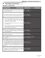
Sequence of operation
OPERATION
DISPLAY
1. The high limit may require reset through the display before
any action will take place.
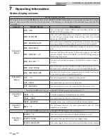
HTR: Standby
OUT: 123.8F( 78)
2. Upon a call for heat the control turns on the unit pump. The
flow switch and low water cutoff (if equipped) must close.
HTR: Standby
OUT: 123.8F( 78)
3. • If the unit is equipped with a proof of closure valve, the
proof of closure switch must be closed. The proof of
closure valve is then energized. The gas pressure
switch(es) (if equipped) must close.
• If the contact for the louvers is closed, the louver proving
inputs must close.
• If the air pressure switch is open, the prepurge cycle then
begins by starting the combustion blower. Once started,
the air pressure switch must close.
HTR: Standby
OUT: 123.8F( 78)
4. After the 15 second prepurge, the blower slows down and
the hot surface igniter (HSI) is energized. The HSI is heated
for at least 20 seconds.
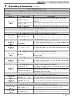
HTR: PREPURGE
OUT: 123.9F( 78)
5. Once the HSI is hot, the trial for ignition begins with the
opening of the gas valve.
HTR: IGNITION
OUT: 123.9F( 78)
6. If the SMART SYSTEM control does not sense flame, then
it will lock out.
HTR: POSTPURGE, LOCKOUT
OUT: 123.9F( 78)
7. If the SMART SYSTEM control senses flame, it will fire the
burner to maintain the set point. The firing rate will stage as
required to hold the actual temperature at the set point. If the
pool heater lights due to a space heating call for heat, and the
ramp delay function is active (default is disabled), the staging
will be held to a series of increasing limits after the burner
has lit.
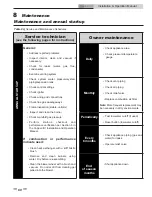
HTR: RUN STG: 1
OUT: 124.8F( 78)
8. Once a call for heat is satisfied, the control will turn
off the burner. The blower will remain on for the 30 second
postpurge cycle. The pump will continue to run for the
respective pump delay times, then turn off.
HTR: POSTPURGE
OUT: 127.4F( 78)


