


Operating Manual
Tangential Rolling System T18F - T27F
22
www.lmt-fette.com
The axial rolling clearance is adjusted as follows: loosen the clamping screw (ET-37).
Place the supplied face spanner on the bushing (ET-13) and rotate in a clockwise
direction until the thread roll can no longer be rotated. Then rotate the bushing (ET-13)
back in a counterclockwise direction until the clamping screw (ET-37) is able to en-
gage in the next groove of the bushing (ET-13). Tighten the clamping screw (ET-37).
Check whether the thread roll can now easily be rotated again. The axial clearance of
the thread roll is now max. 0.05 mm (0.002 inch).
5.1.4
Functional testing
Proper operation of the roll head is ensured when the rolls can be rotated smoothly
and, if one roll is held tight, the other can be rotated to the inner side of the head. Here
the spring is extended in the equalizing gear. When the turned roll is released, it must
rotate back automatically to the initial position.
5.1.5
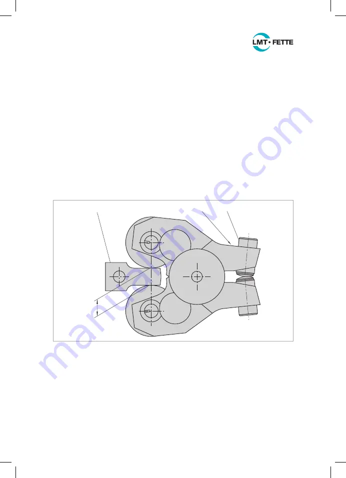
Adjusting the distance between the axes
D
KW
ET-32
ET-28
ET-30
Figure 11: Adjusting the distance between the axes
The distance of the thread rolls – known as the distance between the axes – has to
be set to the required workpiece core dimension by adjusting the two set screws
(ET-30). The set screw (ET-28) is used to lock the set screw (ET-30). Loosen the set
screw (ET-28). The width D
KW
of the setting gauge (ET-32) roughly corresponds to the
minor diameter d
3
of the workpiece (see Figure 11). Adjust the set screws (ET-30) until
the setting gauge fits exactly between the rolls. Make sure that both set screws are
equally adjusted in the upper and lower part to ensure that the hinge is always opened
or closed symmetrically. When the distance between the axes has been adjusted, the
set screws (ET-28) must be tightened again.
LMT_Bedienungsanleitung_T18F_T27F_e.indd 22
02.08.11 17:40