


7
2.0 TROUBLEShOOTING LIQUID END
2.1 LOW PUMP OUTPUT
Low pump output can be caused by many things. Some of the more common ones are:
• Very low stroke setting, i.e. red zone setting of knob
• Trapped air in pump head (trapped air in discharge tubing has no effect)
• Air leak through valve seal rings
• Ruptured pumping Liquifram™ (diaphragm)
• Clogged Liquid End, or injection point connection
• Injection into pressure within 25 psi (1.7 Bar)* of pump’s maximum pressure rating with anti-
syphon spring in place (if so supplied)
• Injection into pressure in excess of pump rating-see chart on page 6.
* 10 psi (0.7 Bar) for Series E74.
A.
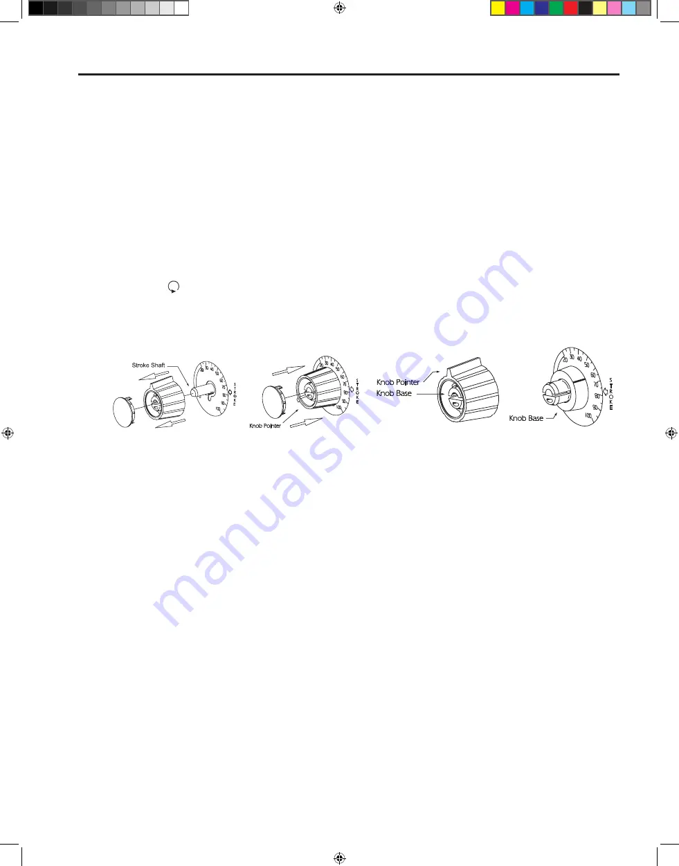
Very low stroke setting
- Check position of stroke length knob (lower knob) by rotating it counter-
clockwise until Liquifram™ (diaphragm) stops moving with the pump operating. The Liquifram™
should not stop reciprocating (moving or clicking) until the knob points to zero. If it stops before
zero, reset knob by grasping the knob and pulling it towards you. Pry the yellow cap off of the knob.
Place the knob on a flat surface. Using needle nose pliers, squeeze the inner section together while
lifting the outer section up (see Figure 5, below).
Push the inner section back onto the “D” shaped stroke shaft. With the pump running, zero the
pump by turning the inner section of the knob counter clockwise. Position the outer section of the
knob so that the pointer aligns with zero on the nameplate. Push down on the outer section of the
knob (a snap sound will indicate that parts are locked together). Replace the yellow cap over the
outer section of the knob, aligning the tabs on the cap with the slots on the knob.
B.
Trapped air in pump head -
May be caused by leaks in the suction line, where the suction line
joins the suction fitting, or at the seal ring between suction fitting and pump head. It may also be
caused by air or gases coming out of solution. Trapped air or bubbles in the discharge line have no
effect on the pump’s operation. They may be ignored.
• To remove trapped air from the pump head, operate the pump with stroke frequency knob and
stroke length knob set at 100.
• It may be neccessary to pull on both knobs of the 4FV, or rotate pressure relief knob ¼ turn, if
so equipped. Follow “Priming” instructions in the Liquid Handling Assembly Sheet inserted in this
instruction book and operate the pump for a few minutes to purge the head and valves of air or gas.
C.
Air leak through valve seal rings-
usually caused by worn or damaged seal rings or loose fittings.
Tighten fittings by hand until they are very snug. If there is no improvement, replace both seal rings
in pump head. See enclosed Liquid Handling Assembly Sheet.
Figure 5
1718.D_306.indd 7
4/4/06 1:21:24 PM


