3 (9)
Pipe installation
Circulation pump
Delivery setting: Constant pressure curve 1.
If parts of the heating system do not get hot,
this can be changed to Constant pressure curve
2. Selecting a higher curve increases energy con-
sumption and operating costs.
Push but-
ton
LEDs
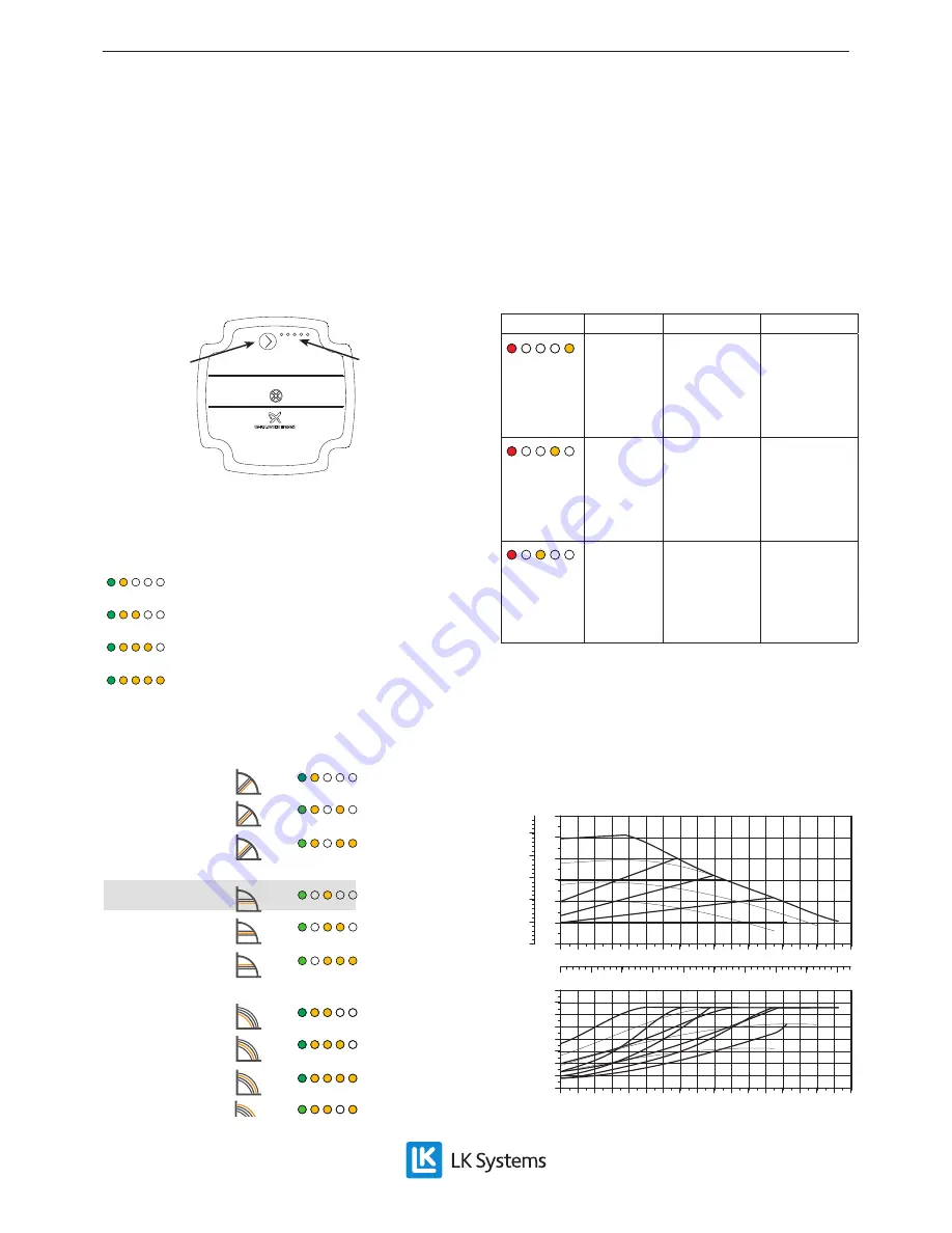
In operating mode, the first LED lights up green,
and between one and four LEDs light up yellow.
The yellow LEDs indicate the operating capacity
of the pump.
0 - 25 %
25 - 50 %
50 - 75 %
75 - 100 %
Pressing the button displays the pump setting for
2 sec before the pump returns to normal display.
PROP. PRESSURE: CURVE 1
PROP. PRESSURE: CURVE 2
PROP. PRESSURE: CURVE 3
CONST. PRESSURE: CURVE 1
CONST. PRESSURE: CURVE 2
CONST. PRESSURE: CURVE 3
CONST. CURVE: KURVA 1
CONST. CURVE: KURVA 2
CONST. CURVE: KURVA 3
CONST. CURVE: KURVA 4
If the button is depressed for 2 sec, the pump
switches to setup mode and the LEDs flash. In
setup mode, any one of 10 curves can be selected
by turning the button. When the button has been
released for 10 sec, the pump returns to operat-
ing mode, the LEDs stop flashing and the selected
curve becomes active.
A lit red LED indicates an alarm or warning.
Indication
Fault
Status
Measure
Red
+
fourth
yellow
Motor
blocked
Pump tries
to restart
at 1.5 sec
intervals
Release
motor/
impeller or
wait
Red
+
third yel-
low
Low volt-
age
Warning
only, pump
continues to
operate
Check volt-
age to pump
Red
+
second
yellow
Electrical
fault
Pump
stopped
Check volt-
age/replace
pump
A button lock prevents accidental adjustments to
the pump settings. The button can be locked/un-
locked by depressing the button for 10 seconds.
After 10 seconds, all the LEDs will flash quickly
to indicate that the lock is locked/unlocked.
Pump capacity
0
1
2
3
4
0.0 0.2 0.4 0.6 0.8 1.0 1.2 1.4 1.6 1.8 2.0 2.2 2.4 2.6 2.8
Q [m³/h]
5
[m]
H
0
10
20
30
40
50
[kPa]
p
0.0
0.1
0.2
0.3
0.4
0.5
0.6
0.7
0.8
Q [l/s]
0
5
10
15
20
0.0 0.2 0.4 0.6 0.8 1.0 1.2 1.4 1.6 1.8 2.0 2.2 2.4 2.6 2.8
Q [m³/h]
25
30
35
[W]
P1
EN.33.C.111.1804


