– 12 –
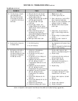
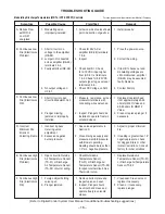
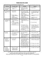
SECTION VII - TROUBLE SHOOTING
Check Safety Shutdown Performace
WARNING: Fire or explosion hazard. Can
cause property damage, severe injury or death.
Perform the safety shutdown test any time work
is done on a gas system.
NOTE: Read steps 1 through 7 before starting, and
compare to the safety shutdown or safety lockout
tests recommended for the intermittent ignition
module. Where diffferent, use the procedure
recommended for the module.
1. Turn off the last manual gas cock.
2. Adjust setpoint above room temperature to call for
heat.
3. Watch for ignition spark following prepurge. See
ignition module speci
fi
cations.
4. Time the length of the spark operation. See the
ignition module speci
fi
cations.
5. After the module locks out, open the manual gas cock
and make sure no gas is
fl
owing to the main burner.
6. Reset the ignition control relay (RE-02).
7. Operate system through one complete cycle to
make sure all controls operate properly.
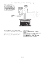
United Technologies Electronics Control Operation
of the Series 1016-400 Direct Spark Ignition
Control (RE-02)
On a call for heat a
fi
ve second pre-purge is initiated.
Upon completion of the pre-purge, the gas valve and
60Hz spark are energized. When
fl
ame is detected,
the control enters the steady state heating condition.
Steady state heating will continue until the call for heat
is satis
fi
ed.
If ignition is not achieved within 15 seconds, the control
shuts off the gas and locks out. If the trial for ignition has
been accomplished without ignition, the control shuts off
all outputs and enters lockout. Reset is accomplished
by cycling the power off for a minimum of 5 seconds. If
fl
ame is lost once it has been established, the control will
shut off the gas valve within 0.8 seconds and locks out.
If
fl
ame is sensed during a purge period when no
fl
ame
should be present, the control will remain in purge with
the gas valve off until the false
fl
ame disappears. If the
gas valve is found to be powered when it should be off, or
not powered when it should be on, the ignition control will
enter lockout with all outputs off. Reset is accomplished
by cycling the power off for a minimum of 5 seconds.
The Red LED Diagnostics codes are:
Steady Off:
No power or control hardware fault
Steady On:
Power applied, control OK
1 Flash:
Burner failed to light
2 Flashes:
Flame was established but then went out.
3 Flashes:
Control hardware fault detected
This equpipment has been electrically and
fi
re tested
prior to shipment. However, during transit control
setpoints can change, and wiring can come loose. Do
not assume controls are defective until all associated
setpoints and wiring are checked.
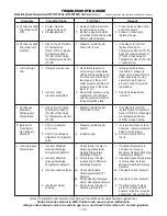
If you do not have the optional BACview 6 (KP-01)
keypad display it will be diffi cult to troubleshoot
any alarm that may occur on the unit. To reset
most alarms on the I/O Zone 583 Controller (UC-01)
without a BACview 6 keypad display, simply turn
the power off and back on at the unit disconnect.
If you have a BACview 6 keypad display the alarm
can be reset remotely or at the I/O Zone 583
Controller.
The following is a simpli
fi
ed list of possible problems
and typical causes and remedies. However, it does
not cover all possibilities, and is intended as a guide
only.
You might also need to reference the Digital
Control System User Manual for additional trouble-
shooting and diagnostics.
WARNING: Many of the steps listed on the
following pages require electrical cabinet and
blower access while the unit is powered. High
voltage and moving parts are present, and these
steps should be performed by qualifi ed service
personnel. If any of the controls requiring
manual reset were at fault this is an indication
of a problem with the system that should be
investigated.


