– 31 –
CIRCUIT ANALYSIS – MAXITROL GAS VALVES
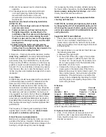
Connect a DC volt meter (capable of reading 0-24V DC) on the Modulator (M611) or Modulator-Regulator
(MR212) Valve terminals.
The operation of the Valve with regard to voltage is as follows: from 0 volts to approximately 5 volts, the modulat-
ing valve should be on bypass
fl
ow with the heater operating on low or minimum
fi
re. From approximately 5 volts
to 15 volts DC, the valve should be performing its modulating function, and the heater should be
fi
ring at a modu-
lated
fl
ow rate between low and high
fi
re, depending upon the voltage. Above approximately 15 volts DC, the Valve
should be delivering full
fl
ow to the heater and the unit should be on full
fi
re. If the DC voltage is obtained on the
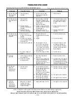
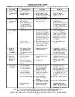
Valve terminals, but the heater does not respond as described, the problem can be isolated to the valve itself or to
the gas control manifold of the heater.
If the proper voltages are not obtained the problem can be isolated to the electronics and/or electronic relay
(RE-26). See the Trouble Shooting Section and the Digital Control System User Manual.
See the Thermistor Output Curve in the following section.
Typical 10,000 Ohm Thermistor Output Curve
0
5000
10000
15000
20000
25000
30000
32
41
50
59
68
77
86
95
104
Temperature in Degrees F
Resistance (Ohms)
SECTION XI - THERMISTOR OUTPUT CURVE


