page 3
INSTALLATION INSTRUCTIONS
FIXTURE PACKING LIST
Description
Quantity
A LED Light Fixture...............................................................................1
B Integrated Mounting Hook .................................................................1
C Wire Nuts* .........................................................................................3
D Safety Cable* ....................................................................................1
*Contained in parts packs
Remove the new LED high bay from packaging and inspect for any
damage. Handle new LED fi xture with care. If damaged do not use;
call your local rep for replacement.
The CPRB models noted as ALO and SWW have a Switchable CCT and
ALO (Adjustable Lumen Output) feature. Please refer to the section CCT/
ALO Selection to adjust the switches. The CCT switch is preset at 5000K
and the ALO switch is preset at 15000lm (ALO13) and 24000lm (ALO14)
from the factory.
The CPRB luminaires have been designed and tested in accordance with
applicable UL/CSA standards and are suitable for use in damp locations.
Max luminaire weight is 6 lbs (2.7kg).
Note: Turn off power at circuit breaker box!
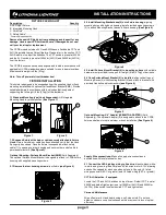
Figure 1
FIXTURE INSTALLATION
Figure 3
1.2 Suspend fi xture with chain or cable securely attached to fi xture
Hook.
Note: after chain or cable has been attached, verify that the Hook
Spring clip has closed. Once the fi xture is suspended, attach safety
cable (1) to opening on driver housing and secure other end of cable to
permanent structure.
(See Figure 2)
.
Optional Mounting- Surface Mount Bracket (SMB)
(Sold Separately)-
The optional Surface Mount Bracket is designed to attach to CPRB fi xture
housing with supplied mounting screws.
2.1
Remove the four housing screws
from fi xture
(see Figure 3)
.
This fi xture is designed to be suspended from the supplied Hook or fl ush
mounting installation with optional Surface Mount Bracket (SMB). Provide
suitable hardware in accordance with local codes that is capable of
supporting the full weight (6 lbs (2.7kg)) of the luminaire.
1.1 Standard Mounting type (Hook Suspended)-
Lift Integrated
Mounting Hook to vertical position
(See Figure 1)
.
2.2 Install Mounting Bracket base (2) onto fi xture housing
aligning
mounting holes with holes on housing. Install provided mounting screws
(3) to attach Mounting Bracket bases to fi xture housing.
(See Figure 4)
.
2.3 Install Surface Mount Bracket (4) to mounting surface
with suitable
hardware (not provided) to support full weight (6 lbs (2.7kg)) of luminaire.
2.4 Once Surface Mount Bracket (4) is installed
, align vertical legs of
Mounting Bases (2) with Mounting bracket (4) and attach to bracket with
provided Hex bolts and lock washers
(see Figure 5)
.
2
3
4
2
Supply Wire connections-
Make all supply wire connections in
accordance with local electrical codes.
3.1 Connect the LED high bay wiring to line wire
, black-to-black, white-
to-white and green-to-green. Purple and Pink wires are for 0-10V dimming
and shall be capped for each wire when not used. Use only UL listed
wiring connectors (90°C or greater) and UL listed wiring (90°C or greater).
CCT/ALO Selection- if equipped
Locate the CCT and ALO Switches on top of driver. Default CCT is set at
5000K and default light output is set at 15000lm (ALO13) and 24000lm
(ALO14). Slide switch to select desired CCT and light output.
Care and Maintenance
Wipe off exterior dirt and debris using a soft, clean cloth. Do not use
abrasive cleaners on optical surfaces as this may result in loss of optical
effi ciency.
Figure 4
Figure 5
1
Figure 2
Optional Mounting- 3/4” Adapter (JEBLMTG ADAPTER)
(Sold
Separately)- The optional Adapter (5) is designed to attach to the CPRB
fi xture and allows for optional stem or hook installation.
(See Figure 6)
Figure 6
5

