background image


34 


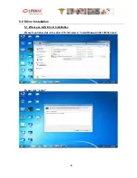
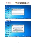
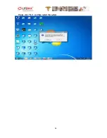
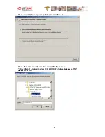
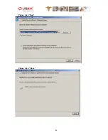
Please click “Yes”, and then restart the system


Summary of Contents for PPS1831 Series

Page 1: ...1 5 All information is subject to change without notice Approved by Checked by Prepared by LITEMAX Electronics Inc 7F 1 No 135 Lane 235 Bau chiau Rd Shin dian Dist New Taipei City 23145 Taiwan Tel 886...

Page 2: ...2 Record of Revision Version Date Remark 1 1 Mar 30 2012 Initial Release 1 2 Apr 02 2012 Second Version 1 3 Apr 04 2012 Third Version 1 4 May 22 2012 Fourth Version 1 5 June 14 2012 Fifth Version...

Page 3: ...al manufacturer Information provided in this document is intended to be accurate and reliable However the original manufacturer assumes no responsibility for its use nor for any infringements upon the...

Page 4: ...sure reliable operation of the product and to protect it from overheating These openings must not be blocked or covered The openings should never be blocked by placing the product on a bed sofa rug or...

Page 5: ...5 Safety Symbol Description The following safety symbols are the further explanations for your reference...

Page 6: ...ticular installation If this equipment does cause harmful interference to radio or television reception which can be determined by turning the equipment off and on the user is encouraged to try to cor...

Page 7: ...l procedure To prevent possible harm to the environment or human health from uncontrolled waste disposal please separate this from other types of wastes and recycle it responsibly to promote the susta...

Page 8: ...on Microsoft Windows is a registered trademark of Microsoft Corporation RTL is a trademark of Realtek Semi Conductor Co Ltd C T is a trademark of Chips and Technologies Inc UMC is a trademark of Unite...

Page 9: ...3 2 HDD Installation 19 3 3 CF Card Installation 21 3 4 Telephone Set Installation 22 3 5 MSR Installation 23 3 6 Power on off Operation 24 4 BIOS Setting 25 4 1 Main Feature Setup 25 4 2 Advance Chip...

Page 10: ...10 6 OSD Setting 44 6 1 Brightness Menu 44 6 2 Audio Menu 45 6 3 Auto Color Menu 46 6 4 Color Temperature Menu 46 6 5 Auto Adjust Menu 47...

Page 11: ...y to protect the system The following contents should be found in the carton 1 x PPS Series Panel PC 1 x IP Phone Set 1 x CD for User Manual and Driver 1 x AC DC Adaptor If any of these items should b...

Page 12: ...12 AC DC Power Adaptor CD for User Manual and Touch Driver Packing...

Page 13: ...ni PCI for WLAN expansion Moreover they feature flexible I O ports such as six USB2 0 one RS 232 two RJ45 for GbE Convenient operation Silent compact mobility and highly integrated multimedia system l...

Page 14: ...ort RS232 X1 Audio Mic in Line out X1 Smart Card Reader X2 RJ 11 at right and left side X1 Four pins DC Input connector X1 DVB T Antenna connector IEC type Internal Connectivity Speaker 2x2W stereo sp...

Page 15: ...c housing Mounting VESA75 VESA100 Dimension 447 2x302 9 7x58 98 mm Net Weight 5 4Kg Environmental Operating Temperature 0 C 40 C Storage Temperature 20 C 60 C Operating Humidity 5 95 40 C non condensi...

Page 16: ...16 2 4 2 Rear View 2 4 3 Buttom View...

Page 17: ...17 2 5 Product Dimension...

Page 18: ...18...

Page 19: ...sensitive electronic components Always ground yourself to remove any static charge before touching the board Modern electronic devices are very sensitive to static electric charges Use a grounding wri...

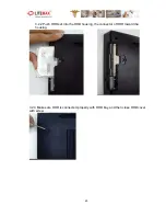
Page 20: ...20 3 2 2 Push HDD set into the HDD housing the connector of HDD toward the housing 3 2 3 Make sure HDD is connected properly with HDD bay and then close HDD cover with screw...

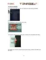
Page 21: ...F card is set in the same bay with HDD 3 2 2 Assembly CF card on the CF carrier metal 3 2 2 Push CF set into the CF housing the connector of CF card toward the housing 3 2 3 Make sure CF card is conne...

Page 22: ...22 3 4 Telephone Set Installation 3 4 1 Tighten the mounting screws on the edge side of phone holder 3 4 2 Put on the IP Phone and connect the phone cable with bottom side RJ11 connector...

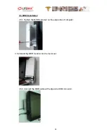
Page 23: ...23 3 5 MSR Installation 3 5 1 Tighten the MSR metal set on the edge side of computer 3 5 2 Assembly MSR module into the metal set 3 5 3 Connect the MSR cable with edge side USB connector...

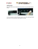
Page 24: ...r on the unit touch the Power on off symbol for 5 seconds till LED indicator lighting 3 6 2 If the computer is working on Windows system power off the unit through OS shut down bottom Or touch the pow...

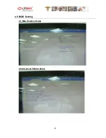
Page 25: ...25 4 0 BIOS Setting 4 1 Main Features Setup 4 2 Advanced Chipset Setup...

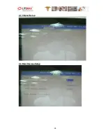
Page 26: ...26 4 3 Chipset Setup 4 4 Boot Devices Setup...

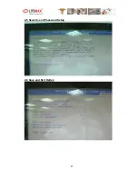
Page 27: ...27 4 5 Security and Password Setup 4 6 Save and Exit Option...

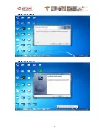
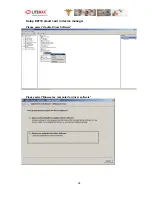
Page 28: ...28 5 0 Driver Installation 5 1 Wire Less LAN Driver Installation Please found driver file in the driver CD file name is Install Bluewu2 3 04 101224 driver Please click Install...

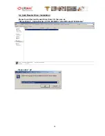
Page 29: ...29 Please click Yes Please click OK...

Page 30: ...30 Please click Next Please select I accept the terms in the license agreement and then click Next...

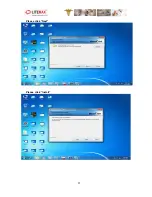
Page 31: ...31 Please click Next Please click Install...

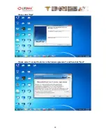
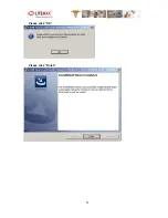
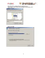
Page 32: ...32 Please click Finish Please click Next...

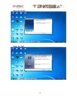
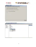
Page 33: ...33 Please click Install Please click Finish...

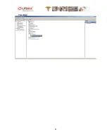
Page 34: ...34 Please click Yes and then restart the system...

Page 35: ...35 5 2 Card Reader Driver Installation Please found the Card Reader Driver from CD file name is Driver Setp 5 Option Castles_SCR RFID Win7 driver Windows7 32bit setup Please click ok...

Page 36: ...36 Please click Next Please click Install...

Page 37: ...37 Please click OK Please click Finish...

Page 38: ...38 Setup EZ710 smart card in device manager Please select Update Driver Software Please select Browse my computer for driver software...

Page 39: ...39 Please found the Card Reader Driver from CD file name is Driver Setp 5 Option Castles_SCR RFID Win7 driver release_ez710 Please click OK Please click Next...

Page 40: ...40 Please click Close Please select Update Driver Software...

Page 41: ...41 Please select Browse my computer for driver software Please found the Card Reader Driver from CD file name is Driver Setp 5 Option Castles_SCR RFID Win7 driver release_ez710 Please click OK...

Page 42: ...42 Please click Next Please click Close...

Page 43: ...43 Completed...

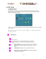
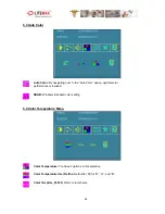
Page 44: ...n you press the menu button you enter the Brightness sub directory In this directory you will see 4 selections OSD Brightness press right key Press the menu once to adjust the brightness Press left to...

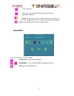
Page 45: ...to adjust the contrast from 0 to 100 To adjust from 100 to 0 press menu and the left buttons Exit You can exit this sub menu back to normal screen 6 2 Audio Menu There are 3 options for Sound sub pag...

Page 46: ...or option optimal color performance is invoked SRGB Windows standard color setting 6 4 Color Temperature Menu Color Temperature You have 3 options in this selection Color Temperature User Define Defau...

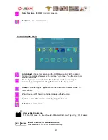
Page 47: ...o tune result you can adjust manually by pressing Clock Using this will make the image wider Phase If double images appear around the characters choose Phase to remove them HPos You can shift the scre...

Reviews: