page 52
02.39 THE CYLINDER BARREL
Before removing any cylinder barrel it should be
marked to ensure it is replace to its original orientation.
Cylinder Barrel Removal
1. Remove the cylinder head and sump.
2. Place a retaining tube, secured by a hand tight
cylinder head nut, over one stud of each cylinder
from which the head was removed.
This will prevent the cylinder rising as the
crankshaft is turned.
3. With the engine turned over and standing on the
flywheel, rotate the crankcase until one connecting
rod big end is at BDC.
4. Remove the big end bearing cap.
5. To protect the crankshaft journal from possible
damage, fit a suitable tube over each connecting
rod bolt and secure it with a hand tight nut.
6. Rotate the crankcase until the same piston is at
TDC.
7. Mark the cylinder for position and number.
8. Remove the tube securing the barrel.
9. Lift off the barrel, piston and connecting rod as a
complete assembly.
10.Remove the tubes from the big end.
11. Replace the big end bearing cap.
12.Remove the piston from the cylinder barrel.
13.Thoroughly clean the cylinder barrel and check for
scoring and wear.
Cylinder Barrel Replacement
1. Fit the piston to the connecting rod.
On TS/TR engines ensure the wording 'CAMSHAFT
SIDE' on the piston crown is the same side as the
identification marks on the connecting rod big end.
2. Insert the gudgeon pin and two circlips; ensure the
circlips are correctly located in the grooves.
3. Fit the piston rings in the order as shown in 'Figure
2.40.1'
4. Ensure the piston ring gaps are staggered and fit
the piston into the cylinder barrel while compressing
the rings.
5. If necessary, fit new big end bearing shells ensuring
they are correctly located in both the connecting
rod and cap.
6. On TS/TR engines:
Coat the bottom jointing face surface of the cylinder
barrel with Hylomar PL32M.
Fit a new joint and coat it with Hylomar PL32M.
7. On TX engines:
Clean and dry the cylinder head clearance shims,
the cylinder barrel and crankcase mating surfaces.
Place the shims, dry, onto the bottom of the
cylinder barrel.
8. Turn the crankshaft crankpin to TDC.
9. To protect the crankshaft journal from possible
damage, fit a suitable tube over each connecting
rod bolt and secure it with a hand tight nut.
10.On TS/TR engines:
Ensure the deeper cylinder barrel fins will be facing
towards the manifold side and 'CAMSHAFT SIDE'
on the piston crown will face towards the camshaft.
10a.On TX engines:
Ensure the connecting rod identification marks will
face towards the camshaft.
11. Lower the cylinder and piston assembly into
position.
12.Push down on the top of the piston as the
crankcase is rotated until the crankshaft crankpin
is at BDC.
13.Remove the protective tubes.
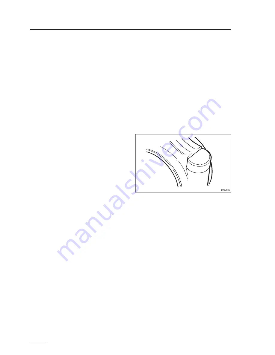
14.Ensure the connecting rod cap bolt head is
correctly located against the shoulder on the
connecting rod as shown below.
15.Fit the big end bearing cap ensuring the
identification numbers are on the same side and
identical.
Figure 2.39.1 Bearing Cap Bolt Head Location
16. Replace the connecting rod nuts and torque them
to 43.5Nm (32.0lbf ft).
It is recommended that connecting rod bolts and
nuts are replaced at every major overhaul.
Section 02
Engine Servicing and Adjustments
- cylinder barrel
Summary of Contents for TR1
Page 1: ...TS TR TX Workshop Manual Edition 12 May 2005 Publication P027 08221 ...
Page 2: ...page 2 ...
Page 80: ...page 80 Section 05 Routine Maintenance TS TR wearing parts TS TR Wearing Parts ...
Page 81: ...page 81 Section 05 Routine Maintenance TS TR wearing parts TS TR Wearing Parts ...
Page 82: ...page 82 Section 05 Routine Maintenance TX wearing parts TX Wearing Parts ...
Page 83: ...page 83 Section 05 Routine Maintenance TX wearing parts TX Wearing Parts ...
Page 90: ...page 90 Section 07 Flywheel Charge Windings Syncro Syncro Fault Finding Flow Charts ...
Page 91: ...page 91 Section 07 Flywheel Charge Windings Syncro Syncro Fault Finding Flow Charts ...
Page 93: ...page 93 Nicsa Fault Finding Flow Charts Section 07 Flywheel Charge Windings Nicsa ...
Page 94: ...page 94 Section 07 Flywheel Charge Windings Nicsa Nicsa Fault Finding Flow Charts ...
Page 95: ...page 95 Section 07 Flywheel Charge Windings Nicsa Nicsa Fault Finding Flow Chart ...
Page 96: ...page 96 ...
Page 98: ...page 98 Section 08 Electrical Wiring Diagrams ...
Page 99: ...page 99 Section 08 Electrical Wiring Diagrams ...
Page 100: ...page 100 Section 08 Electrical Wiring Diagrams ...
Page 101: ...page 101 Section 08 Electrical Wiring Diagrams ...
Page 102: ...page 102 Section 08 Electrical Wiring Diagrams ...
Page 103: ...page 103 Section 08 Electrical Wiring Diagrams ...
Page 104: ...page 104 ...
Page 115: ...page 115 Section 11 Index Section 11 Index a ...


