background image

Lister Petter LT and LV Operators Handbook

page 6

1.3 Technical Data

1.4 Nomenclature

LT1 - single cylinder, direct  injection,

naturally aspirated, flywheel fan air cooled
diesel engine.

Build 32 is convection cooled.
LV1 - single cylinder, direct injection,

naturally aspirated, flywheel fan air cooled
diesel engine.

Build 32 is convection cooled.

1.5 Engine Serial Number

The engine serial number is stamped

on a plate attached to the air shield on
the manifold side of the engine. It is
necessary to identify the type and build
of each engine to enable the correct
maintenance procedures, as described
later in this publication, to be carried out.

Typical Serial Number

03  00123  LV1  C  01

Serial Number Code
03 ........... Year code (03=2003)
00123 ..... Consecutive number of engine
LV1 ......... Model
A ............. Anti-clockwise rotation
C ............ Clockwise rotation
01 ........... Build of engine

1. General Information

- technical data and engine identification

LT1

LV1

Rotation

1

Clock and anti-clock Clock and anti-clock

Type of injection

Direct

Direct

Number of cylinders

1

1

Electrical system

2

12v negative earth

12v negative earth

Battery charging system

2

Charge windings

Charge windings

Oil pressure - minimum

bar

0.4

0.4

lbf/in

2

5.8

5.8

Oil sump capacity

litres

1.3

1.3

pints

2.3

2.3

US qts

1.3

1.3

Capacity between dipstick
marks

litres

0.2

0.2

pints

0.35

0.35

US qts

0.21

0.21

Fuel tank capacity

litres

5.0/8.25

8.25/13.5

pints

8.8/14.5

14.5/23.7

US qts

5.3/8.7

8.7/14.2

Notes:

1. Rotation is dependant on Build - refer to "1.5 Engine Serial Number".

2. Fitted as standard on some builds.

Summary of Contents for L Series

Page 1: ...tors Handbook page 1 THE L SERIES OPERATORS HANDBOOK HANDBOOK CONTENTS page Issue 10 April 2003 Introduction 2 Engine Features 3 1 General Information 4 2 Operating Instructions 7 3 Engine Fluids 11 4 Engine Servicing 13 5 Index 23 ...

Page 2: ...e under different conditions Using this Operators Handbook It is recommended the individual steps contained in the various maintenance or repair operations are followed in the sequence in which they appear When a diesel engine is operating or being overhauled there are a number of associated practices which may lead to personal injury or product damage Your attention is drawn to the symbols shown ...

Page 3: ... and LV Operators Handbook page 3 Engine Features LT1 and LV1 Engine Features LT1 Fuel tank Engine lifting eye Lubricating oil filler LT1 Build 32 Dipstick Air Cleaner Fuel pump LV1 Decompressor lever Fuel tank filler ...

Page 4: ...adequate and the system is primed Ensure that the battery is connected fully charged and serviceable Where possible disengage the driven equipment while starting 1 1 3 Charge Winding Precautions The following points must be strictly observed when charge windings are fitted otherwise serious damage can be done Never remove any electrical cable while the battery is connected in the circuit Only disc...

Page 5: ...Ensure the lifting equipment to be used has the correct capacity to lift the engine A single engine lifting eye is fitted Suitable lifting equipment designed to give a vertical lift from directly above the engine lifting eye must be used Check that the engine lifting eye is not damaged and is secure The lifting eye fitted to the engine is suitable for lifting the engine and accessory assemblies or...

Page 6: ...03 00123 LV1 C 01 Serial Number Code 03 Year code 03 2003 00123 Consecutive number of engine LV1 Model A Anti clockwise rotation C Clockwise rotation 01 Build of engine 1 General Information technical data and engine identification LT1 LV1 Rotation 1 Clock and anti clock Clock and anti clock Type of injection Direct Direct Number of cylinders 1 1 Electrical system 2 12v negative earth 12v negative...

Page 7: ...AUSE UNCONSCIOUSNESS AND DEATH The engines are able to run satisfactorily at ambient temperatures up to 25 C 77 F without derating Above this temperature the rated power must be reduced in accordance with the relevant ISO BS or DIN Standards The maximum temperature is 52 C 125 F and if it is desired to run at higher temperatures the local Lister Petter Distributor or Dealer should be consulted 2 2...

Page 8: ...l position by gently pulling the engine control lever A outward over the middle catch B and turning it fully clockwise Figure 2 4 1 Engine Control 2 If a variable speed control lever is fitted move it to the fast position 3 Move the decompressor lever towards the flywheel Figure 2 4 2 Decompressor Lever 4 If the ambient temperature is below 10 C 14 F refer to 2 3 The Cold Starting Aid 5a If using ...

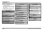
Page 9: ...fitted and remove the handle from the housing Figure 2 4 4 Holding the Starting Handle 8 Turn the engine control lever anti clockwise to the RUN position 9 If a variable speed control is fitted reduce the speed as required 2 5 Electric Starting If the engine fails to start within 30 seconds release the start key or start button and attempt to restart after allowing sufficient time for all moving p...

Page 10: ... 6 Turn the engine control lever anti clockwise to the RUN position 7 If a variable speed control is fitted reduce the speed as required 2 6 Stopping the Engine Turn the engine control fully anti clockwise to the STOP position and hold it there until the engine comes to rest After the engine has stopped ensure the start key if fitted is turned anti clockwise to the OFF position Figure 2 6 1 Engine...

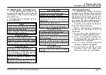
Page 11: ...ce at the lowest temperature likely to be encountered 3 L Series engines must be run on heavy duty lubricating oils that at least meet the requirements of one of the following API CC MIL L 46152B DEF2101D MIL L 2104B Straight mineral oils are not suitable neither are oils of less detergency than specified Note Higher specification oils meeting API CD API CE and API CF 4 are more commonly available...

Page 12: ... 10W 30 oils may be used at up to 52 C 126 F but oil consumption may be affected 10W 40 15W 40 and 20W 40 multigrade oils are recommended for continuous full load operation at this temperature 4 Monograde SAE 40 oils are not recommended 3 4 Fuel Specification The engine must only be used with diesel fuel oil which conforms to one of the following a BS 2869 1988 Class A2 b BS EN590 1995 Class A1 c ...

Page 13: ...tly or indirectly connected to the engine It is essential to ensure that nuts and bolts are tightened to the torques specified in the Workshop Manual When re assembling an engine lubricate all moving parts with engine oil Renew nuts and bolts that have been taken from high stress locations In particular nuts and or bolts from the connecting rods should be renewed The fuel injector can only be chec...

Page 14: ...pecified in 4 13 Maintenance schedule hours It is recommended that the following receive attention after the engine has run 50 hours and again after 250 hours Adjust the valve clearances if necessary Check and tighten nuts bolts and unions paying particular attention to the fuel system Check the lubricating oil level and top up if necessary Observe the exhaust at the normal full load The exhaust m...

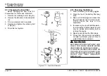
Page 15: ...djusting screw and re check to ensure the clearance is correct 6 Repeat for the remaining valve 7 Replace the rocker cover taking care to ensure the decompressor lever is vertical 4 Engine Servicing valves and decompressor adjustment 4 6 Decompressor Adjustment This adjustment should only be made when the valve clearance is correctly adjusted 1 Remove the cylinder head cover 2 Turn the flywheel un...

Page 16: ... start Builds 1 Remove the air cleaner from the manifold by removing the centre bolt A taking care to retain the copper washer Figure 4 8 1 Air Cleaner 2 Remove the cover B by unscrewing the centre bolt C 3 Remove the old element D and fit a new one 4 Engine Servicing air cleaner 4 9 Air Cleaner other Builds 1 Remove the cover A by removing the centre bolt Figure 4 9 1 Air Cleaner 2 Remove the old...

Page 17: ...eads of the flanged drain plug with Wellseal and the tapered plug with Hylomar PL32 M or Three Bond 1110B 5 Replace the drain plug taking care not to over tighten it 6 Fill the sump through the oil filler to the top mark on the dipstick B Figure 4 10 2 Oil Filler 7 Start the engine run it for a few minutes and check the drain plug does not leak 8 Stop the engine allow the oil to settle and check t...

Page 18: ...plug area 3 Remove the filler plugs and check that the electrolyte level is 6 0 9 0mm 0 25 0 37in above the tops of the separators 4 If necessary top up with distilled water In cold weather distilled water should only be added immediately before running the engine 5 Replace and tighten the filler plugs 6 Check that the terminal connections are tight petroleum jelly will help to protect them from c...

Page 19: ... conditions Every 125 Hours The above and the following items Check the conditionof the battery if fitted Clean or replace the air cleaner element under moderately dusty conditions Every 250 Hours The above and the following items Drain the sump and refill with new oil of the correct type and specification as given in 3 1 Oil Specification Clean or replace the injectors if the exhaust is dirty Ren...

Page 20: ...moke generally as a result of water in the fuel Faint blue smoke appears with light load Heavy blue smoke caused by lubricating oil passing the piston rings due to stuck worn or broken rings or a worn cylinder Black smoke due to incomplete combustion of the fuel can be caused by overload choked air filter inlet air temperature too high or incorrect specification of fuel Overheating Air inlet obstr...

Page 21: ...top the engine and drain the lubricating oil from the sump The crankshaft should NOT be turned until the engine is again required for service The inhibition fluid should be left in the fuel system e Seal all openings on the engine with tape f Remove the batteries and store them fully charged after coating the terminals with petroleum jelly g Grease all external bright metal parts and the speed con...

Page 22: ...Lister Petter LT and LV Operators Handbook page 22 ...

Page 23: ...ter 18 Fuel for low temperatures 12 Fuel specification 12 H Hand starting 8 I Initial attention 14 Introduction 2 L Long term storage 21 M Maintenance schedule hours 19 N Nomenclature 6 O Oil specification 11 Oil sump 17 Oil viscosity 12 Operating instructions 7 P Priming the fuel system 14 R Running in 2 S Safety precautions 4 5 7 14 Safety symbols 5 Serial number 6 Stopping the engine 10 T Techn...

Page 24: ... Published in April 2003 by Lister Petter Printed in the United Kingdom Lister Petter UK Limited Dursley GL11 4HS England CALIFORNIA Proposition 65 Warning Engine exhaust and some of its constituents are known to the State of California to cause cancer birth defects and other reproductive harm ...

Reviews: