TME-104P-CSR-LX800-R1V11.doc
Rev 1.11
27 (50)
3.14
Reset-In Signal
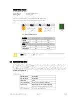
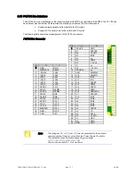
The "Reset-In" signal is located on the IDC10 Header PS/2. To reset the board, the signal "Reset-In" must be
pulled to GND.
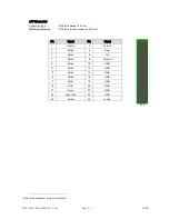
Connector type:
IDC10 pin header 2.54 mm
Matching connector:
IDC10 pin female connector 2.54 mm
Pin
Signal
Pin
Signal
1
Speaker
2
Mouse Clock
3
Reset-In
4
Mouse Data
5
KB Data
6
KB Clock
7
GND
8
+5 Volt Switched
9
Ext. Battery
10
Power Button
3.15
Internal Battery
On the board a soldered battery type CR1225 is used to keep RTC time and date running if the board is not
powered. The battery can be connected or disconnected to the RTC with the battery jumper set to ON or OFF. As
default on delivery the jumper is set to OFF. It is recommended to set this jumper if the board is used in the
application and to remove the jumper if the board is stored for a longer period. This will prevent the battery from
discharge.
3.16
External Battery
A connected battery should replace or support the mounted one to keep date and time active during the board is
mechanical off.
It is recommended to use a model with 3 Volt, but it will also work with power suppliers up till 3,6 Volt.
The time and date will be lost if the power supplier falls down to 2,4 Volt.
For live time calculation there are 2 µA (25°C) needed when the board is not running.
That value can rise up with higher temperatures.
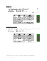
Connector type:
IDC10 pin header 2.54 mm
Matching connector:
IDC10 pin female connector 2.54 mm
Pin
Signal
Pin
Signal
1
Speaker
2
Mouse Clock
3
Reset-In
4
Mouse Data
5
KB Data
6
KB Clock
7
GND
8
+5 Volt Switched
9
Ext. Battery
10
Power Button
X16
X16

