TME-104P-CSR-LX800-R1V11.doc
Rev 1.11
15 (50)
LVDS Configuration
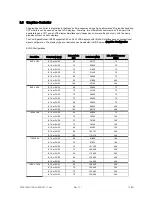
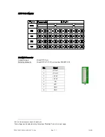
The display options of LVDS are shown in the table:
Setting
Possible Values
Flat Panel Type
LVDS
Resolution
320x240, 640x480, 800x600, 1024x768,
1152x864, 1280x1024, 1600x1200
Data Bus Type
18/24 Bits, 2ppc
Refresh Rate
60 70, 72, 75, 85, 90, 100 Hz
HSYNC Polarity
High, Low
VSYNC Polarity
High, Low
LP Active Period
Active Only
à
only active during SYNC
Free Running
à
always active
SHFCLK Active Period
Active Only
à
only active during SYNC
Free Running
à
always active
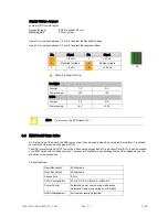
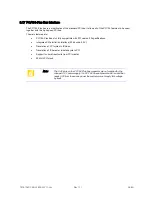
To ease usage of these displays it’s possible to select the display and backlight supply voltages with the onboard
voltage selector jumpers. (Jumper LVDS and Backlight, see below)
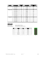
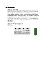
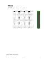
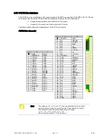
LVDS Connector
Connector type:
Hirose DF13 2x 10-pin header
Matching connector:
Hirose DF13-20DS-1.25C, part number 536-0555-6 00
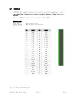
Pin
Signal
Pin
Signal
2
SW-VDD
3
1
SW-VDD
3
4
GND
3
GND
6
TX3+
5
TX3-
8
TXCLK-
7
GND
10
GND
9
TXCLK+
12
TX2+
11
TX2-
14
TX1-
13
GND
16
GND
15
TX1+
18
TX0+
17
TX0-
20
DDC DATA
19
DDC CLK
3
1.0 A is the maximum current for each pin
X7

