Copyright © 2016 Lintest Systems, LLC – All rights reserved 09/17/2016
Hardware Installation
Installing the PiCapture hardware is straightforward:
1.
Connect the CSI-2 Ribbon Cable
Hold the PiCapture board above the Raspberry Pi and make sure that
it is oriented so that the 40-pin connectors will mate. Pull up on the
ribbon cable locking mechanism, insert the ribbon cable, and push
down on the locking mechanism to secure the cable.
2.
Mount the PiCapture board to the Raspberry Pi
Carefully connect the 40-pin connectors along the side of the boards.
Use the provided screws and spacers to secure the PiCapture board to
the Raspberry Pi.
Note that the size of the mounting holes may vary slightly, and it may
be necessary to gently ream out the holes slightly for the screws to fit.
3.
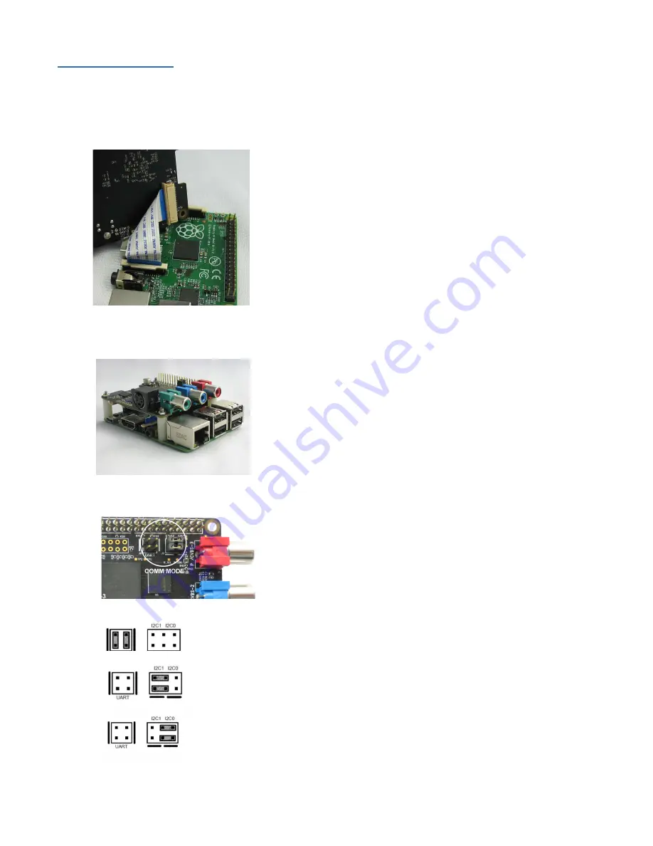
Check the interface jumpers
The jumpers used to select the communications mode are located
directly behind the red RCA connector. There are two blocks: a 2x2
block used to enable serial communication, and a 2x3 block used to
select either I2C0 or I2C1.
The jumpers should be placed vertically on the block marked “UART” for serial
communication
The jumpers should be placed horizontally on the left using the pins marked
“I2C1” for i2c communication on port 1. This is the default configuration.
The jumpers should be placed horizontally on the right using the pins marked
“I2C0” for i2c communication on port 0.


