background image

17 


Select 

Services 

 In/Out

, the 

In/Out

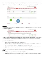
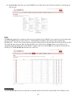
 page is displayed below. The 

In/Out

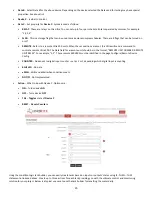
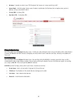
 page has the relay controls and the input controls on one 

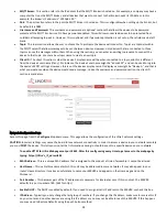
page. The Ultra 300 SERVER has two relay outputs, two digital inputs and two analog inputs. The relay is named as Relay 1 and Relay 
2, digital input is named DIN1 and DIN2, analog input is named AN1 and AN2, you can change the names as desired.  


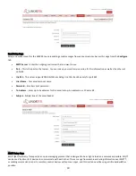
Relay Control 

On the 

In/Out

 page, the first section is the 

Relay Control, 

here you can set the relay property based on your application. Each relay 

has a number, in this case 1 to 2. 

The 

State

 LED show whether the relay is on or off indicated by GREEN and RED respectively. This icon is clickable to manually control 

the corresponding relay. Each relay can have a Name as well as identifiers for the Normally Open, Common and Normally Closed 
connections.  

There are four status LEDs that show:  


Email


 If an email is to be sent when this relay is switched on and off 


Pulse


 If this Relay is set with a pulse width and pulse width multiplier (duration) 

 see next section for more information 


Sched

 If there is schedule created in the 

Tasks

 page set to automatically trigger this relay. 


Timed


 If pulse is set and this relay is activated, the 

Timed

 LED will turn red showing the relay is currently operating on a 

timer. 

Click the 

Edit 

Icon to edit the controls for the corresponding relay. This will take you to the 

Set Relay 

page. 

Set Relay  

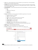
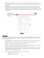
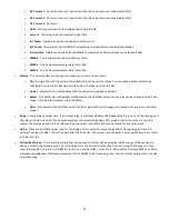
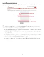
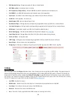
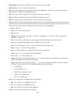
The SET RELAY page allows you to set various properties pertaining to the Relay.  


Relay Select

 - The Relay that you are editing is identified by the line on which you clicked the Edit icon on the RELAY page.  

Summary of Contents for iTrixx-Ultra 300

Page 1: ...iTrixx Ultra 300 User Manual www linortek com Preliminary For Ultra 300 with Hour Meter Software ...

Page 2: ...2 ...
Page 3: ...Accessing the SERVER 13 Finding your IP Address with Linortek Discoverer 13 Finding the IP address by connecting to USB port on Your PC 14 Connecting your SERVER directly to Your PC 14 Software Configuration 15 Landing Page 15 Home 15 Services 16 In Out Page 16 Hours Page 22 Tasks 23 Set Schedule Page 23 Logs 26 Settings 27 User and Admin Credentials Page 27 Time Date Page 27 Settings Page 28 Conf...

Page 4: ...4 System 33 Load Reboot System Page 33 Data Collection 35 Hour Collector App 35 DataCollector Pro App 35 RESTful API 35 MQTT 35 JSON file 35 ...

Page 5: ...ting the product 2 Retain Instructions Retain the safety and operating instructions for future reference 3 Heed Warnings Adhere to all warnings on the product and in the operating instructions 4 Follow Instructions Follow all operating and use instructions 5 Cleaning Unplug the product from power before cleaning Do not use liquid cleaners or aerosol cleaners Use a damp cloth for cleaning the enclo...

Page 6: ... a metal appliance or pipe While changing the batteries or fuses do not touch i any wires other than the battery wires and ii the printed circuit board LIMITATION OF LIABILITY IN NO EVENT WILL LINOR TECHNOLOGY BE LIABLE WHETHER IN CONTRACT TORT OR OTHERWISE FOR ANY INCIDENTAL SPECIAL INDIRECT CONSEQUENTIAL OR PUNITIVE DAMAGES INCLUDING BUT NOT LIMITED TO DAMAGES FOR ANY LOSS OF USE LOSS OF TIME IN...

Page 7: ...n the Software You may not disclose the results of any performance or functional evaluation of any of the Software to any third party without the prior written consent of Linortek for each such release 3 Updates Linortek may from time to time develop updates upgrades patches bug fixes and other modifications Updates to improve the performance of the Software Except as otherwise provided on the Lin...

Page 8: ...enue You agree that this EULA and any claim dispute action cause of action issue or request for relief arising out of or relating to this EULA will be governed by the laws of the state of North Carolina U S A without regard to conflicts of laws principles provided that if you reside in a country that will not apply U S law to disputes related to these terms then the laws of your country will apply...

Page 9: ...tra 300 SERVER ____One 12VDC Power Supply ____Micro USB to 12V Jack ____One CAT5 Patch Cord ____One DIN Rail Mount Clip ____iTrixx Ultra 300 Quick Setting Instruction ____One 2 2k OMETER Resistor Kit The SERVER is designed to be integrated into existing equipment Installing your SERVER will involve tapping circuits on the equipment you intend to monitor IN NO EVENT WILL LINOR TECHNOLOGY BE LIABLE ...

Page 10: ...the inputs to turn counting on and off There are two digital inputs in the SERVER The digital inputs allow the SERVER to detect an external on off state of a sensor 3 Alternatively it can be configured to follow one of the relays such that when the relay is activated the SERVER will count There are two relay outputs and are simply numbered OUT1 and OUT2 on the SERVER These relays are dry contact r...

Page 11: ... you can use a USB cable to connect it to your computer to power it on and find out the IP address from your network Alternatively you may also use POE At this point the GREEN Boot LED should come on and start flashing indicating the SERVER is operating and is in the Bootload Mode This mode allows the user to update the server software that is used on the unit After about 5 seconds the GREEN LED w...

Page 12: ...ther an input is on or off count events in a resettable or non resettable counter and calculate the frequency such as for use as a tachometer or the period of the input There are two modes of operation for the digital inputs PULL UP and ISOLATED PULL UP mode connects a 1K resistor to an internal voltage allowing you to use a simple switch such as a magnetic door switch across terminals 1 and 2 Thi...

Page 13: ...inortek Discoverer The Discoverer program will automatically locate your SERVER The Discoverer is a Java program and requires Java Runtime to be installed to use this feature Java can be found here http java com en download index jsp To download the Discover program please go to https www linortek com downloads support HYPERLINK https www linortek com downloads supportprogramming programming Use o...

Page 14: ...C using Device s POWER input Open any terminal emulator you prefer and set your COM port to Serial You can find your COM port number under Device Manager open the window and type netinfo command You will get your Ultra s IP address Connecting your SERVER directly to Your PC You can also plug your SERVER directly to your PC in the case there is no network connection available If you plug your SERVE...

Page 15: ...ername and password default username and password admin admin These credentials will be retained by the browser until the browser is closed You can disable the password requirement in Settings User and Admin Credentials page The landing page displays the following settings Two meters Each Ultra 300 includes two separate hour meters with independent triggers Each meter can record 999999 99 hours de...

Page 16: ...s should blink about once per second as long as the server is running The GREEN LED is used for bootloader options and is generally not visible on the website The BLUE LED is clickable and you can turn it on and off from this web page This is useful for locating the device physically should it be in use with other similar units as it will illuminate on the unit to which this web browser is connect...

Page 17: ...ing relay Each relay can have a Name as well as identifiers for the Normally Open Common and Normally Closed connections There are four status LEDs that show Email If an email is to be sent when this relay is switched on and off Pulse If this Relay is set with a pulse width and pulse width multiplier duration see next section for more information Sched If there is schedule created in the Tasks pag...

Page 18: ...can access relays physically on the SERVER or using other means You may select Normal relay physically on the SERVER Latched not currently supported Remote a relay on another Linortek device access over the network Zigbee a relay at a remote device access over an RF system Normal and Remote both relays activated Normal and Zigbee both relays activated Remote BELL to turn on a bell at remote locati...

Page 19: ...ended to turn on only those you want to use Type The input data can be used to calculate a range of results You may select State This is useful for knowing if an input is on or off like a door switch being on or off CounterNR This is a non resettable counter CounterR This is a resettable counter Frequency Counts the frequency of an input in KHz kilo hertz or1 1000 seconds This could be useful in d...

Page 20: ... name the display as well as associate a relay with it This relay will change from Green to RED as it goes from on to off as well as is clickable to control it Analog Input Selected The Analog Input that you are editing is identified by the line on which you clicked the Edit icon Name You can set a 15 character name for this input This name goes in the bar at the top of the display Label Set a 7 c...

Page 21: ...ored per the Color ranges The Label is displayed within the Meter VBar Also based on the Min Max values for the scale and the bar changes color based on the values in the Color ranges Relay Enter a Relay number here If it is a local relay it will show GREEN or RED depending if it is on or off By clicking on it the relay will turn on and off The name comes from the relay settings page This may be u...

Page 22: ...age Threshold condition must be satisfied along with the trigger condition to make the meter count This is useful to stop the counter should the unit start to lose power For example by setting a threshold of 20 volts on a 24 volt system the Hour Meter will assume that the power is declining and shut off to prevent a counter memory error 7 Send Email Using the Email checkbox and the Count the unit ...

Page 23: ...OR NOT b THEN c This provides a simple to program and powerful way to take advantage of the data acquired by the Ultra The Tasks page shows you an overview of configured tasks You can click the dot in the State column to turn a task on or off indicated by a green dot for ON and a red dot for OFF To edit or create a task click the Edit icon to the right of the task line This will take you to the Se...

Page 24: ... 5 Friday 6 Saturday 7 Weekday 8 Weekend 9 Time Enter hh mm use leading zeros seconds are ignored use 24 hour system ex 07 30 or 14 05 Date Enter yy mm dd use leading zeros ex 20 01 10 for January 10 2020 Relay Enter Relay number and or ex 01 for Relay 1 ON or 01 for Relay 1 OFF Button Enter or for ON or OFF respectively Flag Enter Flag number opt or Flag number for ON or OFF respectively Temp Ent...

Page 25: ...te unit should be in the format REMOTE UNIT NUMBER REMOTE UNIT RELAY For example 3 5 These remote SERVERS must be identified in the page Configure Remote Device Config COUNTER Add count to digital input counter set as 1 or 2 depending which digital input is counting BLUE LED No data eMAIL Will send eMail when condition meets NOTIFY Not Implemented Action What to do with Device C Options are ON Tur...

Page 26: ...user to filter logs from different sources To filter out logs you do not wish to see from a certain source simply uncheck the box Each log has a reference number and a time and date attached in a yyyy mm dd and hh mm ss format Afterwards is the event displayed To scroll through the logs use the arrows to the right hand side where the horizonal line and arrow brings you to the start or end the doub...

Page 27: ...ively The passwords are never displayed Password length are limited to 13 characters If you set a password longer than the limits you won t be able to login to the account Active Must be checked for this user to sign on you cannot deactivate User 1 Admin Only admin can save data in most pages This protects your SERVER from being changed by an unauthorized person Timeout Not enabled at this time Ti...

Page 28: ...d select this option to Log every NTP event May be useful in debugging Settings Page Access this page from the Settings dropdown menu Select these settings to enable various features in the Ultra 300 Use Active Main No longer used Select PAUSE to go inactive Require Login If not selected the SERVER will allow all access without credentials Use IP Ranges Not Implemented Use RESTFUL IP Ranges Not im...

Page 29: ...ings may be vary depending on application Not required for hour meter software Select theme Choose theme color red green blue Change Logo Choose your Company s Logo to replace Linortek logo max size 60kB format png file Configure Dynamic DNS Page Access this page from the Configure dropdown menu From this page you can assign dynamic DNS settings This page along with proper port forwarding through ...

Page 30: ...x only for port 465 User Name Your email account name Password Email account password To Address Enter up to 3 addresses for this email set up An addressee a CC and a BC Subject Subject line of the email header MQTT Setup Page MQTT MQ Telemetry Transport is an open messaging protocol that is designed to be as light a load on a network as possible MQTT can be used by all sorts of devices to communi...

Page 31: ...the devices display name Its display name might be Device A and that is what you would see when the device would send a message Unlike the username and password section the client ID section is mandatory Network Configuration Page Access this page from the Configure dropdown menu This page allows the configuration of the Ultra s network settings CAUTION Incorrect settings may cause the board to lo...

Page 32: ...may cause the board to lose network connectivity Currently not available for future use Remote Devices Page Access this page from the Configure dropdown menu These settings allow the SERVER to remotely control the relays on other Linortek devices Peer to Peer communication This is done by selecting the Remote Device in the Schedule program or by setting up a relay as a REMOTE There are 8 possible ...

Page 33: ...button about 10 15seconds until the RED LED comes on steady blinks at 1 second rate To locate the RESET RELOAD buttons please check Board Layout Reference section in this manual 2 There is an equivalent RESET DEFAULTS function in the web browser at System Load Reboot System page Check the Restore Default Values box then click the Boot Mode button your device will be reset to factory default once t...

Page 34: ...34 get a message MPFS Updated Successful then click the Site main page you will be directed to the Login page On the bottom of every page you can see your Webpage Software version ...

Page 35: ...y acquire data This is useful for port forwarded network hour meters as it can go out to the internet and read data off the device s XML pages It can also collect data from the iTrixx WiFi Hour Meter both via REST or subscribe to an MQTT broker For more information about the features for the app as well as how to use the data saved by the app please refer to the Linortek DataCollector App Setting ...

Reviews: