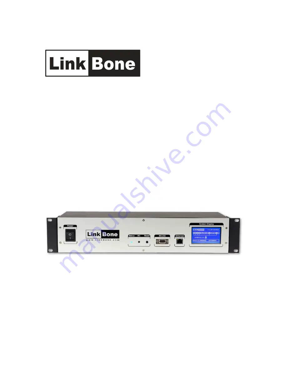
LinkBone Switch
Type: 8x8 Matrix/Dual 8x8 Matrix
User manual
Version 0.9
Copyright © 2014 LinkBone. All rights reserved.
Page 1: ...LinkBone Switch Type 8x8 Matrix Dual 8x8 Matrix User manual Version 0 9 Copyright 2014 LinkBone All rights reserved...
Page 2: ...Display 11 4 1 Main screen 11 4 2 Screen settings 13 4 3 Infrared Remote Control settings 14 4 4 Ethernet settings 16 4 5 RS 232 settings 18 5 Ethernet remote control port 19 5 1 HTTP server 19 5 2 Te...
Page 3: ...or external cables Touching device ground and elements with the different electric potential can result in electric shock In order to connect external equipment to LinkBone Switch the user should alw...
Page 4: ...to the LinkBone Switch ports If emission requirements are not met the user should tune the signal sources to reach an acceptable level of the EM emission If guarantee seals are broken or removed the m...
Page 5: ...r defects caused during transport In case of damage of shipped goods please keep the complete shipping container and filling Before the first run of the device please check that none of the instrument...
Page 6: ...l voltage levels and current values The block diagram illustrating the connection of input output ports is shown in figure 1 Ports with symbols from A to H represent matrix column and ports from I to...
Page 7: ...5 1 HTTP server Telnet server accepting text commands described in chapter 7 Text commands accepted by LinkBone Switch 8x8 Matrix Dual 8x8 Matrix type The switch control via RS 232 interface is done b...
Page 8: ...ecifications a The BNC port version has the following pin connections Center nut port signal line Shield ground connection b The XLR port version has the following pin connections pin numbers are incl...
Page 9: ...ts described in chapter 10 Specifications Plug the power adapter into your AC power outlet Figure 4 shows the power connection diagram Figure 4 Connection of the LinkBone Switch to the power outlet To...
Page 10: ...crews are tightened at there is no loose connection between the unit housing and the handle Four oval shaped holes on the mounting handles are used for unit installation into rack rails The equipment...
Page 11: ...a square point on line crossing The signal paths crossings without a square point mean that there is no connection To modify matrix connection status tap on the column or row ports marked by arrow on...
Page 12: ...u contains the following items Screen System Display settings described in chapter 4 2 Screen settings IR Remote Control infrared remote control options The RC5 IR remote control is described in chapt...
Page 13: ...fter 10 seconds 30 sec switch off the screen after 30 seconds 1 min switch off the screen after 1 minute 2 min switch off the screen after 2 minutes 5 min switch off the screen after 5 minutes 10 min...
Page 14: ...es not respond to the received RC5 codes Assign RC5 code assigns the RC5 remote control code to current switch port state After assigned RC5 code is received the device will change its switch port sta...
Page 15: ...emote Control menu If user presses the assigned remote control button in the future the switch will change its statstate to programmed value The switch configuration includes port connection setup and...
Page 16: ...t port mode with two possible values o Mode DHCP device operates in DHCP client mode The DHCP server assigns the IP address subnet mask and default gateway In this mode it is not possible to modify ot...
Page 17: ...fy related setting value The edit window is shown on figure 16 At the top of the screen edited parameter is displayed The user can edit parameter value by using the numerical keys and navigate between...
Page 18: ...d length odd parity bit is transmitted o 8 bits even parity 8 bit data word length even parity bit is transmitted Stop bits specifies the number of stop bits between data words This parameter defines...
Page 19: ...atrix type For proper operation of network services a configuration of Ethernet settings is required The configuration is described in chapter 4 4 Ethernet settings 5 1 HTTP server To access HTTP serv...
Page 20: ...using the checkbox and then clicking Apply changes Ticked Checkbox means that the connection will be enabled Empty checkbox means that there will be no connection Matrix nodes with connection enabled...
Page 21: ...of the client enter the device IP address and port 23 After successful connection to the server a welcome message is displayed The system accepts text commands described in Chapter 7 Text commands acc...
Page 22: ...a terminal on remote computer figure 21 Before establishing the connection parameters of RS 232 serial interface need to be set as described in chapter 4 5 RS 232 settings The LinkBone Switch accepts...
Page 23: ...quit closes current session this command is only available for a Telnet clients Remarks All commands are case sensitive mode parameter can have two values o single only one connection is allowed betw...
Page 24: ...ith a lint free dry cloth Please take care to not scratch the display when cleaning 9 Product recycling The LinkBone Switch complies with the requirements of RoHS standard concerning the use of hazard...
Page 25: ...andard 38Khz Ethernet interface o Standards o Connector type o Supported cable types 10 100 Ethernet RJ45 STP Cat5E up to 100m length RS 232 serial interface o Baudreate o Transmission type o Transmis...
Page 26: ...26 LinkBone Switch User manual 8x8 Matrix Dual 8x8 Matrix type 11 Appendix A Electromagnetic Compatibility...
Page 27: ...L DAMAGES INCLUDING BUT NOT LIMITED TO PROCUREMENT OF SUBSTITUTE GOODS OR SERVICES LOSS OF USE DATA OR PROFITS OR BUSINESS INTERRUPTION HOWEVER CAUSED AND ON ANY THEORY OF LIABILITY WHETHER IN CONTRAC...