13
dc1605bf
DEMO MANUAL DC1605B
Demo BoarD use cases
USE CASE #3
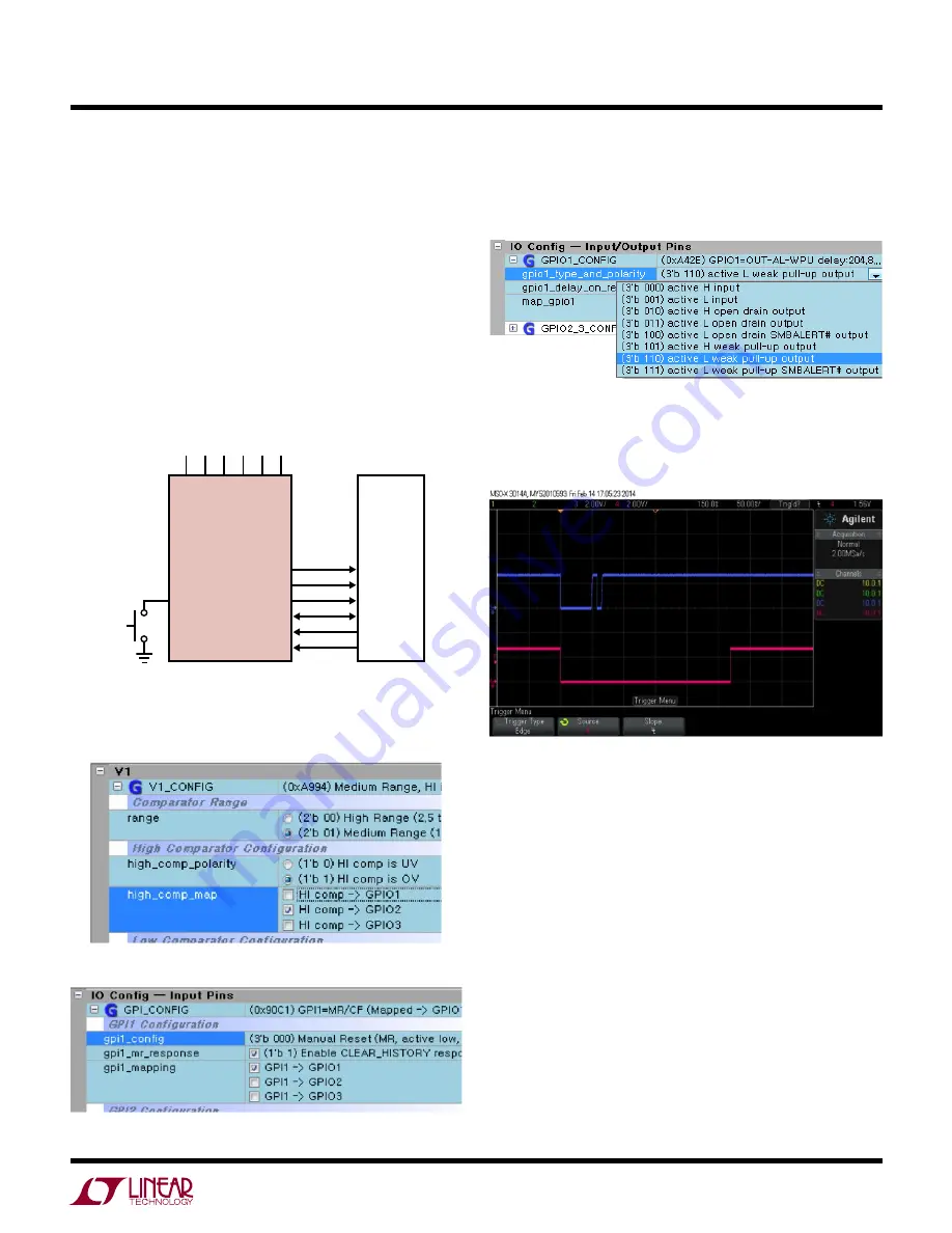
Another common configuration is one that uses a GPIO
pin to drive a system reset. The LTC2936 data sheet shows
this feature throughout. The other two GPIOs are config-
ured as previously shown, OV and ALERT. Additionally a
manual reset pushbutton (GPI1) asserts the system reset.
GPIO1
→
RST (system reset)
GPIO2
→
OV
GPIO3
→
ALERT
GPI1
→
MR pushbutton
LTC2936
SYSTEM
V1 V2 V3 V4 V5 V6
GPIO1
GPIO2
GPIO3
SDA
SCL
GPI2
GPI1
MR
RST
OV
ALERT
MARG
1. To program GPIO1 to system reset function, first
uncheck the hi_comp mapping of all V1-V6 channels
to GPIO1.
2. Configure GPI1 as a Manual Reset. Map GPI1 to GPIO1.
3. Configure GPIO1 as active-low with weak pull-up. To
update the changes made in steps 1-3, click the Write
All Registers (PC
→
RAM) icon.
4. You can optionally extend the low time of the system
reset by changing the delay-on-release setting to ensure
a clean release of reset. This provides a time-based
debounce of the switch.
When configured in this way, GPIO1 provides a system reset
for the host processor and GPI1 can drive a system reset
(GPIO1) with a push of a button. You may set the GPIO1
delay-on-release time to 410 ms to experience the extended
reset firsthand. The UV condition indicator remains on
GPIO3. The OV condition is indicated as a latched ALERT
on GPIO2. When GPI1 pushbutton is pressed, a system
reset is asserted on GPIO1 and the ALERT is released if
the OV condition is removed.


