background image


LTL HABMM 

Issue 2.0 

Page A1-5 

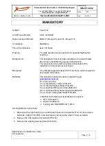
Parachute Centering Lines 

Each line must be checked for correct length, no 
abrasions, all knots secure 


Shroud Lines and Upper 
Pulley 

Shroud lines in good condition, knots secure 


Upper pulley in good condition, free running 


Pulley lubricated with silicone spray 


Velcro Tabs 

Clean and free of debris 


Holding force good 


Stitching intact 


Parachute Fit 

Overlap equal around circumference 


No daylight visible 


No excessive tension in centering lines 


No excessive stress wrinkles at parachute edge 


Visible seal between parachute fabric and hole 
edge 


FAST DEFLATION SYSTEM


Pulleys or Rings at Parachute 
Edge 

Pulley undamaged, sheave spins freely 


Inspect rings for wear 


No abrasion on attachment loop 


Verify presence and condition of line stoppers when 
pulleys are at end of kevlar centering lines 


Pulleys or Rings at Side of 
Envelope 

Pulleys undamaged, sheave spins freely 


Inspect rings for wear 


Check condition of attachment loop 


Internal Load Tapes Cross on 
Centre Patch 

Check stitching is secure 


Check attachment of FDS solid red line or bridle 
lines 


Summary of Contents for Racer 56

Page 1: ... 671888 Fax 44 0 1691 679991 www lindstrandtech com All rights reserved No part of this Manual may be reproduced or transmitted in any form or by any means electronic or mechanical including photocopy recording or any information storage and retrieval system without permission in writing from Lindstrand Technologies Ltd Maesbury Road Oswestry Shropshire SY10 8HA England ...

Page 2: ...y of DOA EASA 12J 176 Amendments This manual is kept up to date by amendments consisting of loose leaf pages required to add new information or amend existing information The pages affected by an amendment and the effective date are shown above The pages themselves are identified by a change of the issue number at the bottom of each page The number after the point in the issue number represents th...

Page 3: ...appropriate CHECKLIST OF PAGES Page No Issue Page No Issue i ii iii iv v 1 2 3 4 5 6 7 8 9 10 11 12 13 14 15 16 17 18 19 20 21 22 23 24 2 0 2 0 2 0 2 0 2 0 2 0 2 0 2 0 2 0 2 0 2 0 2 0 2 0 2 0 2 0 2 0 2 0 2 0 2 0 2 0 2 0 2 0 2 0 2 0 2 0 2 0 2 0 2 0 2 0 A1 1 A1 2 A1 3 A1 4 A1 5 A1 6 A1 7 A1 8 A1 9 A1 10 A1 11 B1 1 B1 2 C1 1 C1 2 C1 3 C1 4 C1 5 C1 6 C1 7 C1 8 2 0 2 0 2 0 2 0 2 0 2 0 2 0 2 0 2 0 2 0 2...

Page 4: ...on may have specific features for dedicated systems every balloon has a dedicated manual showing the serial number on the cover Always make sure before proceeding that you have the correct manual issue The Maintenance Manual does not always make a distinction what work can be carried out by the operator and what can only be serviced by factory personnel If in doubt always consult the manufacturer ...

Page 5: ...ion 2 3 Mandatory Replacement Time 2 4 Structural Inspection Interval 2 5 Structural Inspection Procedure 2 6 Acceptable Damage SECTION 3 TECHNICAL DESCRIPTION 3 1 Envelopes 3 2 Baskets 3 3 Burners 3 4 Fuel Systems SECTION 4 PREVENTATIVE MAINTENANCE 4 1 Paperwork 4 2 Envelopes 4 3 Baskets 4 4 Fuel Systems 4 5 Burners SECTION 5 REPAIR AND MAINTENANCE 5 1 Envelopes 5 2 Envelope Repairs 5 3 Baskets 5...

Page 6: ... 6 2 Load Bearing Attachments 6 3 Burner 6 4 Fuel Cylinders 6 5 Baskets 6 6 Fabric Strength Test 6 7 Inspection After Overheating 6 8 Inspection After Hard Landing APPENDICES A 1 Appendix A Annual 100 Hour Inspection Checklist B 1 Appendix B Envelope Repair and Damage Record C 1 Appendix C All Figures ...

Page 7: ...BILITY The information contained within this manual applies to all hot air balloons manufactured by Lindstrand Technologies Ltd under EASA Approval see Section 3 Technical Description for a comprehensive list of models covered 1 3 IDENTIFICATION OF SYSTEMS A serial number and a description identify all major components of Lindstrand Technologies hot air balloons These are located as follows Envelo...

Page 8: ...s thought to have occurred then a fabric strength test should be carried out It is at the discretion of the inspector to carry out a grab test below 250 hours of flight if fabric degradation is thought to have occurred 2 5 INSPECTION PROCEDURE The Inspection Procedure can be found in Section 6 of the Maintenance Manual The Inspection Check List is specified in Appendix A of the Maintenance Manual ...

Page 9: ... a fuel leak it must be repaired or replaced before the balloon may be flown BASKET When there are more than five strands of a basket wire broken it must be repaired or replaced before the balloon may be flown BASKET PLYWOOD FLOOR If the plywood floor has separated from the lower stainless frame or if the floor is damaged so that a 250 mm crack is visible on both sides of the floor the basket must...

Page 10: ... base of the envelope and scoop are comprised of a fire resistant Nomex material A parachute is located at the top of the envelope and allows for the controlled release of hot air Partial opening of the parachute valve can be used to cool the balloon Some Lindstrand Technologies balloons are also equipped with turning vents which allow for the pilot to turn the balloon on its vertical axis while i...

Page 11: ... on basket occupancy see Flight Manual Section 2 1 8 3 3 BURNER The Lindstrand Vortech burner is effectively the engine of the hot air balloon The burner system consists of burners two and fuel lines that carry LPG from the fuel tanks to the burners The burners convert ambient air into hot air which in turn provides the lift required for flight The fuel is supplied to the burner assembly through t...

Page 12: ...k For description see Figure 2 Appendix C 3 4 FUEL CYLINDERS Fuel cylinders are equipped with a main liquid valve a float gauge pressure relief valve and ullage valve The main liquid valve regulates the flow of the liquid propane to the burner The float gauge provides a reading of the remaining capacity of the tank in a percentage The pressure relief valve allows for the release of propane from th...

Page 13: ...tained within this section of the Maintenance Manual must be documented with an entry in the balloon log book which includes the following information a A description of the work performed b The date of completion of the work performed c The name of the person who made the repair or approved it d The total number of hours on the balloon when the work was performed 4 2 ENVELOPES 4 2 1 Cleaning and ...

Page 14: ... assuring the existing knot is duplicated It is not permitted to shorten either line 4 3 BASKETS 4 3 1 Cleaning Storage and Re Varnishing Baskets should be stored in a cool dry area Mud which has dried onto the basket can be removed using a garden hose Padding can be cleaned using a suitable suede or leather cleaner as appropriate The cushion floor foam can be cleaned using detergent and water Bas...

Page 15: ...stones on the ground when placing the cylinder down this is often the most common cause of small dents in the base of the cylinder CAUTION Avoid dropping cylinders on hard surfaces as this may dent or distort the foot ring 4 4 3 Transportation of Cylinders Cylinders should be transported standing upright Transporting cylinders on their sides should be avoided and could cause damage to their intern...

Page 16: ...g with the burner erected on the nylon rods is not advised It will subject it to repeated jarring and can damage the burner the burner frame associated connectors to the burner and the upper basket frame If this is unavoidable a thorough inspection of the burners all connectors toggle valve handles burner to frame interface frame to rod interface and rod to basket interface is advised prior to the...

Page 17: ... repair and maintenance of the aircraft Envelope Construction Materials Colour Type Dimensions Rip Stop Nylon Multiple Colours High tenacity woven ripstop nylon with a soft polyurethane fluorocarbon elastomeric coating 1 5 metre Roll width Longlife Nylon Multiple Colours Taffeta weave heavy nylon base cloth with a silicone elastomeric coating 1 5 metre Roll width Diamond Weave Multiple Colours Hig...

Page 18: ...ster or Nylon 25 mm wide Bottom Rim Load Tape White or Black Polyester or Nylon 50 mm wide Sewing Main Thread White or Grey Metric 30 three strand continuous filament polyester of bonded construction Treated to provided extra resistance to ultra violet exposure 900d 450d x2 300d x3 Denier Sewing Bobbin Thread White or Grey Metric 30 three strand continuous filament polyester of twisted constructio...

Page 19: ...res must meet the Lindstrand Technologies specification It is important that the correct ferrule is used in the swaging process All ferrules must be copper It is recommended that any damaged stainless steel cables should be replaced only with pre assembled cables acquired from Lindstrand Technologies 5 1 3 Fibre Joint Fabric Velcro The fibre joint fabric used structurally is the 50 mm 2 wide stand...

Page 20: ... of any load tape or seam a Contact Cement Patch Standard Fabric A contact cement patch should be cut from matching balloon fabric and may be applied on the inside or the outside of the envelope making an effort to align the ripstop fabric pattern The cement product should be applied to both the patch and the envelope per the adhesive manufacturer s instructions The same 25 mm overlap beyond the d...

Page 21: ...f partial and full panel replacement The damaged panel may be cut away as close as possible to the original folded seam The replacement panel is folded as it would be in a true French fell but the panels do not actually interlock The replacement panel will overlay the original panels which surround it and no raw fabric edge may be exposed The stitching thread must comply with Section 5 1 1 and mus...

Page 22: ...ng tape as shown in Section 5 1 2 3 e Pass the new tape through the Nomex pocket f Turn the tape inside the envelope and stitch through both layers of tape and the sandwiched fabric with the stitch patterns For diagram see Figure 5 Appendix C 5 2 10 Envelope Cables Stainless Stainless steel cables that are slightly discoloured due to overheating are safe provided they have not become too flexible ...

Page 23: ...l lengths and tied in a loop at the mid point Re tie the resulting ends of the pull down lines to the loops on the edge of the parachute and re attach the loop to the quick link The quick link screw gate should be fastened tightly and secured using loctite glue 5 2 13 Parachute FDS Deflation Line For damage near the basket end an additional loop of line is provided at the termination side in the e...

Page 24: ...e hide should be allowed to dry causing it to harden Note Replacement floors are available from Lindstrand Technologies Alternatively the old floor can used as a pattern Holes will need to be cut similar to the removed floor to allow access for the wires Care should be taken to ensure the same thickness and material type is used for both the new floor and the replacement runners For further inform...

Page 25: ...nt can be maintained in a work shop environment When any work is performed on the burners it is very important to ensure that a high standard of cleanliness is achieved Components should be cleaned and dried with soft lint free cloth or left to dry naturally Once any type of service work has been performed on the burner a functional test must be conducted to ensure there are no fuel leaks within t...

Page 26: ...entifying components of the balloon should be checked and verified to ensure agreement with the components actually installed in the balloon presented for inspection On successful completion of the inspection the return to service must be documented with the following or similar entry I have inspected this aircraft using procedures approved by the manufacturer for the completion of a Annual 100 ho...

Page 27: ...ng correctly The parachute should be repaired replaced and inspected to ensure that the parachute is correctly adjusted f Check all load tapes for security of stitching especially around the crown ring and where the overlying tapes join the top rim tape g Check the load tape loops that connect the envelope cables to the envelope There should be no burn damage or fraying of the load tape 6 1 5 Para...

Page 28: ...nce and there should be no daylight visible There should not be excessive tension in any of the retaining lines or radial stress wrinkles at the parachute edge 6 2 LOAD BEARING ATTACHMENTS 6 2 1 Envelope Cables All envelope cables on Lindstrand Technologies balloons are manufactured from stainless steel Replacement with galvanised mild steel is not acceptable For stainless steel envelope cables ch...

Page 29: ...rcraft fuel system they must be replaced with approved parts 6 4 FUEL CYLINDERS Check for external damage to the pressure vessel Damage to the protective top and bottom rings is not critical provided there is no damage to cylinder body at points where these rings are attached Check the operation of the contents gauge Check that when no hoses are connected the self sealing function of the liquid co...

Page 30: ...ction is required If the indicated temperature of the temperature tags is 127ºC or greater a fabric inspection is required Pay particular attention to the edges of the parachute fabric and the parachute retaining lines Excessive heat on fabric tends to cause cracking due to stiffness Discoloration is also another sign of overheating If any signs are visible then a fabric strength test should be co...

Page 31: ...D WORK ORDER NO BASKET PART NO SERIAL NO TOTAL TIME if different from envelope BURNER PART NO SERIAL NO TOTAL TIME if different from envelope FUEL CYLINDERS 1 PART NO SERIAL NO TOTAL TIME if different from envelope 2 PART NO SERIAL NO TOTAL TIME if different from envelope 3 PART NO SERIAL NO TOTAL TIME if different from envelope 4 PART NO SERIAL NO TOTAL TIME if different from envelope ...

Page 32: ... Registration Certificate Present and current Strikers Present and functional Fire Extinguisher Present and in good condition Maintained in accordance with manufacturer ENVELOPE ID Plate Present numbers match log book Fabric Strength if required see Section 6 6 Envelope areas Parachute areas outer edge of parachute overlap 9 kg 25 mm grab test over 75 mm span 1 test warp and weft in each colour 14...

Page 33: ...stitching secure No damage to load tape envelope cable connection Carabiners Free of distortion No corrosion or rust Locking gates operate freely Scoop Envelope attachments secure and undamaged Lower attachments secure and undamaged Envelope cables No visible heat damage no reduction of flexibility No abrasion damage or kinks No more than one broken wire strand No distortion of thimbles or ferrule...

Page 34: ...elt damage Condition good Pulley in good functional condition Turning Vent Rigging Green Line No abrasion or melt damage Condition good Pulley in good functional condition Vent Flag Lines and Stainless Ring or Pulley No twisting or knotting No abrasion damage or fraying All knots in good condition Crown Line Length correct No abrasion damage Attachment clip present and in good condition Crown Ring...

Page 35: ...xcessive tension in centering lines No excessive stress wrinkles at parachute edge Visible seal between parachute fabric and hole edge FAST DEFLATION SYSTEM Pulleys or Rings at Parachute Edge Pulley undamaged sheave spins freely Inspect rings for wear No abrasion on attachment loop Verify presence and condition of line stoppers when pulleys are at end of kevlar centering lines Pulleys or Rings at ...

Page 36: ...good condition Check gimbal tension in both directions Carabiners Free of distortion No corrosion or rust Locking gates operate freely Coil Assembly Coils straight all welds secure Coil support brackets straight and secure no missing stainless rivets Check main jets for blockage and tightness Slurper tubes secure and positioned over the low point of the block Pilot Light Pilot light cup secure che...

Page 37: ...Hose Connector Good overall condition no dents or corrosion Threads in good condition Mates to tanks and or manifolds Functional test for ease of connection and leaks Check valve for self seal function Lubricated with silicone grease spray Tema Hose Connector Good overall condition no dents or corrosion Inner and outer O rings in good condition replace if damaged All bearings free and lubricated L...

Page 38: ...permitted Attachment to stainless frame secure Check integrity of plywood at skid bolts Rawhide or Bottom Scuff Leather Check general condition and lacing secure Cables and Covering Cables undamaged Thimbles in good condition Vinyl tubing sleeves in good condition Heat shrink at swaged area intact Stainless Steel Top and or Bottom Frame Shape correct not bent Top Bolster Padding and Leather Suede ...

Page 39: ...sharp bends in hoses No conflict with other equipment Fuel lines in good condition No cuts or abrasions No bulging or swelling Hose end fittings in good overall condition no dents or corrosion O Rings and square rings in good condition replace if necessary Tema inner and outer O rings in good condition replace if damaged Tema ball bearings free and lubricated Tema locking ring functional Mates to ...

Page 40: ...rotective caps present and in good condition Pressure relief valve clean and covered 15 valve operation checked Tightness of 4 fuel quantity gauge screws checked Tank body free of dents or gouges Tank welds in good condition Tank covers in good condition PRV and Internal inspection within date Cylinder manufactures maintenance manual checked for any further checks required ...

Page 41: ...LTL HABMM Issue 2 0 Page A1 11 INSPECTION DAMAGE LOG DAMAGE AREA OR COMPONENT RECOMMENDATION SIGNED ...

Page 42: ... REPAIR INSPECTION CHART FOR SERIES 1 24 or 28 GORE ENVELOPE RANGE Panel 1 2 3 4 5 6 7 8 9 10 11 12 13 14 15 16 17 18 19 20 21 22 23 24 25 26 27 28 Init Date PARA Z Y X W V U T S R Q P O N M L K J I H G F E D C B A Model No Serial No Registration No ...

Page 43: ...APPENDIX B LTL HABMM Issue 2 0 Page B1 2 LOWEST NYLON PANEL DESIGNATION 70 P 120 S 210 V 300 Y 80 Q 150 T 240 W 310 Z 105 R 180 V 260 X ...

Page 44: ...LTL HABMM Issue 2 0 Page C1 1 APPENDIX C FIGURES AND DIAGRAMS Figure 1a Series 1 24 Gore Envelope ...

Page 45: ...LTL HABMM Issue 2 0 Page C1 2 Figure 1b Series 1 28 Gore Range 28 GORE SERIES 1 HORIZONTAL CUT ...

Page 46: ...LTL HABMM Issue 2 0 Page C1 3 Figure 1c Series Racer 24 Gore Range 24 GORE SERIES RACER HORIZONTAL CUT ...

Page 47: ...LTL HABMM Issue 2 0 Page C1 4 Figure 2 Overview of Vortech Double Burner ...

Page 48: ...LTL HABMM Issue 2 0 Page C1 5 Figure 3 Load Tape Repairs ...

Page 49: ...LTL HABMM Issue 2 0 Page C1 6 Figure 4 Overlying Tape Repairs ...

Page 50: ...LTL HABMM Issue 2 0 Page C1 7 Figure 5 Envelope Cable Loop Repairs ...

Page 51: ...LTL HABMM Issue 2 0 Page C1 8 Figure 6 Bowline Knot ...

Reviews: