Lindab WH45P Technical Manual Download Page 7

 ovER vIEW


WH45P


7

/42

rev 20-10

1.9. 

Mechanism type

Mechanism type selection must be done according to na-
tional legislation and according to building type where fire 
damper will be installed. In particular it must be considered 
if fire protection or smoke detection system need specific 
control over the fire damper or if periodic controls (such as 
opening and closing) are required.
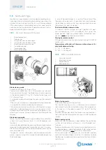
1.9.1. 

Manual / Manual with magnet

1. 

Manual opening lever

2. 

Protection box

3. 

Lever position when the blade is open

4. 

Lever position when the blade is closed

5. 

Magnet knob (for magnetic version)

6. 

Closed blade indicator

7. 

Open blade indicator

8. 

Manual closing button

Blade closing mode

Automatic closing with thermal fuse.
The control mechanism has a thermosensitive element 
that automatically closes the blade when the temperature 
in the duct exceeds 70°C (or 95°C for the fire damper with 
95°C thermal fuse).
It is possible to close the damper by pressing the indicated 
button.
If the manual mechanism is equipped with electromagnet 
it is possible to remotely close the fire damper.
The manual command mechanism with magnet is equip-
ped with an electromagnet which, in case power is inter-
rupted (interuption magnet version) or when power is sup-
plied (input magnet version), comands the closing of the 
damper.

Blade opening mode

Make sure that the damper is open before the ventilation 
system start-up, otherwise there is a risk of product mal-
function.
In case of closed damper by pressing the closing button or 
remotely by electromagnet (magnetic version), it is possi-
ble to manually open the fire damper blade by rotating the 
lever antyclockwise.
For power supply interruption electromagnet, provide 
power supply and pull the magnet knob before opening 
the fire damper.

In case of closed damper as a result of the action of the 
thermosensitive element, it is possible to manually reopen 
the damper by rotating the lever counterclockwise once 
the element has been replaced.

Position indication microswitches

on request, the fire damper can be supplied with posi-
tion microswitches (SA/SC/S2 optional) that signal the 
blade position (open or closed). Refer to Electrical con-
nections  p. 26 paragraph for more details.

Closing by remote control

With power supply input or interruption magnet (WH45PM 
version only).

Temperature calibration of thermosensitive element for 

automatic damper closing

70 °C±7 °C (Standard)
95 °C±9 °C (on request).
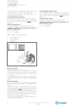
1.9.2. 

Belimo motorized version

1. 

Manual closing switch

2. 

Manual opening lever

3. 

Position indicator

4. 

Blade locking lever

Blade closing mode

Automatic closing with thermal fuse.
The control mechanism has a thermosensitive element 
that automatically closes the blade when the temperature 
in the duct or in the room exceeds 72°C (or 95°C for the 
95°C version).
To close the damper when the motor is connected, press 
the switch on the temperature sensor or cut off the power 
supply.

Blade opening mode

Make sure that the damper is open before the ventilation 
system start-up, otherwise there is a risk of product mal-
function.
To open the damper with the electric motor driven actua-
tor, provide power supply to the motor. Refer to the section 
Electrical connections  p. 26 for further information.
To manually open the damper, use the handle supplied 
and carefully rotate clockwise to the 90° indicator. To hold 
the damper in open position operate on the lever indica-
ted in figure.

WH45P


7

We reserve the right to make changes without prior notice

Summary of Contents for WH45P

Page 1: ...FIRE DAMPER CIRCULAR SERIES WH45P 500 Pa 300 Pa Cert N 1812 CPR 1107 Technical Manual WH45P WH45P lindab we simplify construc tion Technical Manual Installation type with fire resistance class English...

Page 2: ...This is a 42 page manual...

Page 3: ...p 21 3 11 Installation within vertical light wall gypsum blocks wall p 22 3 12 Installations within floor p 23 3 13 Installations within vertical wall with Fire Batt Weichschott sealing p 24 3 14 Inst...

Page 4: ...erial Lip seal on blade border for cold smoke seal Internal intumescent gasket for hot smoke seal 1 3 European Standards applied CE certification EN 15650 Test EN 1366 2 Classification EN 13501 3 Ther...

Page 5: ...ax 800 min 200 max 800 min 200 max 800 EI 180 S Installation within vertical rigid wall p 19 Wall minimum thickness 150 mm Wall minimum density 500 kg m Mortar sealing ve i o W min 200 max 800 min 200...

Page 6: ...x 800 min 200 max 800 min 200 max 800 Minimum distance allowed between 2 dampers 200 mm 50 mm 50 mm 50 mm Flexible wall EI 120 S Installation within vertical light wall plasterboard with Fire Batt Wei...

Page 7: ...kwise For power supply interruption electromagnet provide power supply and pull the magnet knob before opening the fire damper In case of closed damper as a result of the action of the thermosensitive...

Page 8: ...the damper when the motor is connected press the switch on the temperature sensor or cut off the power supply Blade opening mode Make sure that the damper is open before the ventilation system start...

Page 9: ...0 0 0 0 35 80 Lp mm 45 45 45 45 45 45 45 Lp Overlap length between fire damper and duct 2 1 1 Manual 2 1 2 Manual with magnet 2 1 3 Siemens motorized version 2 1 4 Belimo motorized version 2 2 Weight...

Page 10: ...from atmospheric conditions use in explosive environments use on board of ships use in cooker extraction hoods use in pneumatic conveying systems of dust or corn use in ventilation systems within loc...

Page 11: ...case of fire It is recommended not to compress flexible connectors in the installation phase Flexible connector must be at least 100mm long and in order that possible duct thermal expansions are balan...

Page 12: ...ion for transfer appli cation is conform to section Fire resistance classification according to EN 13501 3 2009 p 5 limited to EI 120S if the ducted classification is higher End cap with mesh shall be...

Page 13: ...cap length mechanism side L2 End cap length mechanism opposite side 3 6 3 How to order transfer Application Code Type EPNF End cap with mesh Diameter XYZ Nominal diameter dimension mm Length XYZ Leng...

Page 14: ...r putty sealing 50 75 EI 90 S Installation within vertical rigid wall p 19 Plasterboard and rock wool 100 kg m sealing 50 75 Flexible wall EI 120 S Installation within vertical light wall plasterboard...

Page 15: ...rtical light wall gypsum blocks wall with Fire Batt Weichschott sealing p 24 Rock wool 140 kg m and endothermic varnish sealing 50 50 Floor EI 90 S Installation within floor and Fire Batt Weichschott...

Page 16: ...ht plasterboard vertical walls During testing light plasterboard walls have been used with the following characteristics U shaped horizontal metal frame 50 mm and C shaped vertical frame 49 mm made fr...

Page 17: ...ween each other vertical profile fixing with selfthreading screws or by clin ching to the bottom horizontal profile and insertion in the top horizontal profile profiles fixed using self threading scre...

Page 18: ...damper 3 8 5 Aerated concrete floors Aerated concrete floors can be built during installation or with preformed slabs with interlocking shaped edges ac cording to the following characteristics minimu...

Page 19: ...mper 3 9 3 Filling Fill the space between the wall and the damper as indica ted in the table and in the drawing Sealing with concrete is not allowed Fire resistance classi fication D hole size mm Damp...

Page 20: ...see table above Lp Overlap length between fire damper and duct see section Dimension p 9 EI 120 S EI 180 S Installations within vertical rigid wall 1 Mortar M 10 EN998 2 or plaster putty D Hole size s...

Page 21: ...per protrusion from the wall E mm Wall minimum thick ness S mm Sealing EI 90 S Installation within vertical light wall plasterboard Wall rock wool density up to 100 kg m optional EI 90 S 500 Pa Da 35...

Page 22: ...he damper as indica ted in the table and in the drawing Sealing with concrete is not allowed Fire resistance classi fication D hole size mm Damper protrusion from the wall E mm Wall minimum thick ness...

Page 23: ...loor and the damper as indica ted in the table and in the drawing Sealing with concrete is not allowed Fire resistance classi fication D hole size mm Damper protrusion from the floor E mm Floor minimu...

Page 24: ...CFS S ACR minimum thickness of 1 mm Fire resistance classi fication D hole size mm Damper protrusion from the wall E mm Wall minimum thick ness S mm Sealing Rigid wall EI 120 S Installation within rig...

Page 25: ...k wool panels with minimum thickness of 50 mm and minimum density of 140 kg m The panels must be covered on both faces of the wall with endothermic varnish type PROMASTOP E PASTE or HILTI CFS CT minim...

Page 26: ...ition 1 NC contact of SC microswitch When the fire blade is closed the circuit is open 2 NO contact of SC microswitch When the fire blade is closed the circuit is closed 3 NC contact of SA microswitch...

Page 27: ...d power consumption Power interrruption magnet P 4 5W 24V DC or 230V AC version Power input magnet P 4 5W 24V DC or 230V AC version Motor 24V AC DC WH45PVMB Belimo BFN24T Opening 4W In stand by 1 4W M...

Page 28: ...ble Check damper cleanliness and clean where necessary Check the condition of blades and seals rectify and re port where necessary Check the correct opening and closing of the fire dam per by manual o...

Page 29: ...2676 54 1 3090 58 5 355 3046 49 1 3730 55 2 4307 59 6 400 4244 50 2 5198 56 3 6002 60 7 450 5888 51 3 7211 57 4 8326 61 8 500 7891 52 2 9664 58 4 Qmax 560 10812 53 3 13242 59 4 Qmax 600 13098 53 9 Qma...

Page 30: ...level graph 200 560 Example Diameter mm 315 mm Q Air flow m h Q 3000 m h V1 Frontal air speed m s V1 10 7 m s P Pressure drop Pa From graph P 37 7 Pa Lw Sound level dB A From graph Lw 56 dB A WH45P 3...

Page 31: ...Pa From graph P 36 Pa Lw Sound level dB A From graph Lw 59 dB A 6 6 Sound spectrum table Correction used to estimate the octave band spectrum Values to be added to the noise levels in dB A Frontal spe...

Page 32: ...when power is not supplied Power supply 24V DC 4 5W WHKMG024KIT Remote control magnet optional for manual command fire dampers Power supply interruption version the fire damper blade closes when power...

Page 33: ...BFN230T BF230T Siemens motor for dampers predisposed for use with GGA126 GNA126 GRA126 24V AC DC power supply thermofuse 72 C GGA126 GNA126 GRA126 Siemens motor for dampers predisposed for use with G...

Page 34: ...ST WHKBKN230 24LON Modbus Communication and power supply unit BKN230 24MOD for Belimo motors BFL24T ST BFN24T ST and BF24T ST WHKBKN230 24MOD Communication and power supply unit MPBUS for BKS24 9A or...

Page 35: ...ir sealing 300 Pa for Fire Batt Weichschott installations Command type B Manual command M Manual command with magnet Position indication microswitches S0 Without position microswitches not recommended...

Page 36: ...0 250 300 315 355 400 450 500 560 600 630 710 800 Belimo M M M M M M M M M M M G G Siemens S S S S P P P P P P P G G Belimo Siemens 24V 230V 24V 230V S GRA126 GRA326 P GNA126 GNA326 M BFN24T BFN230T G...

Page 37: ...eter bigger than 315 mm as per EN 1751 Casing leakage class B minimum for diameter less than or equal to 315 mm as per EN 1751 class C on request Installation Installation within vertical rigid walls...

Page 38: ...att Weichschott sealing p 25 Maintenance and inspections p 28 Updated table Electrical specifications p 27 Motorized fire dampers p 35 Electric motor driven actuators p 36 Accessories and spare parts...

Page 39: ......

Page 40: ......

Page 41: ...tly improving its products the aesthetic or dimensional features the technical data the equi pment and accessories indicated could be subject to variations www lindab com Fire dampers are manufactured...

Page 42: ...easy to use as well as offering efficient availability and logistics We are also working on ways to reduce our impact on our environment and climate We do that by developing methods to produce our sol...

Reviews: