Subject to modificaitons
User Manual
Installation and Operating Instructions
2.1EN-38021-D09
Form 403013
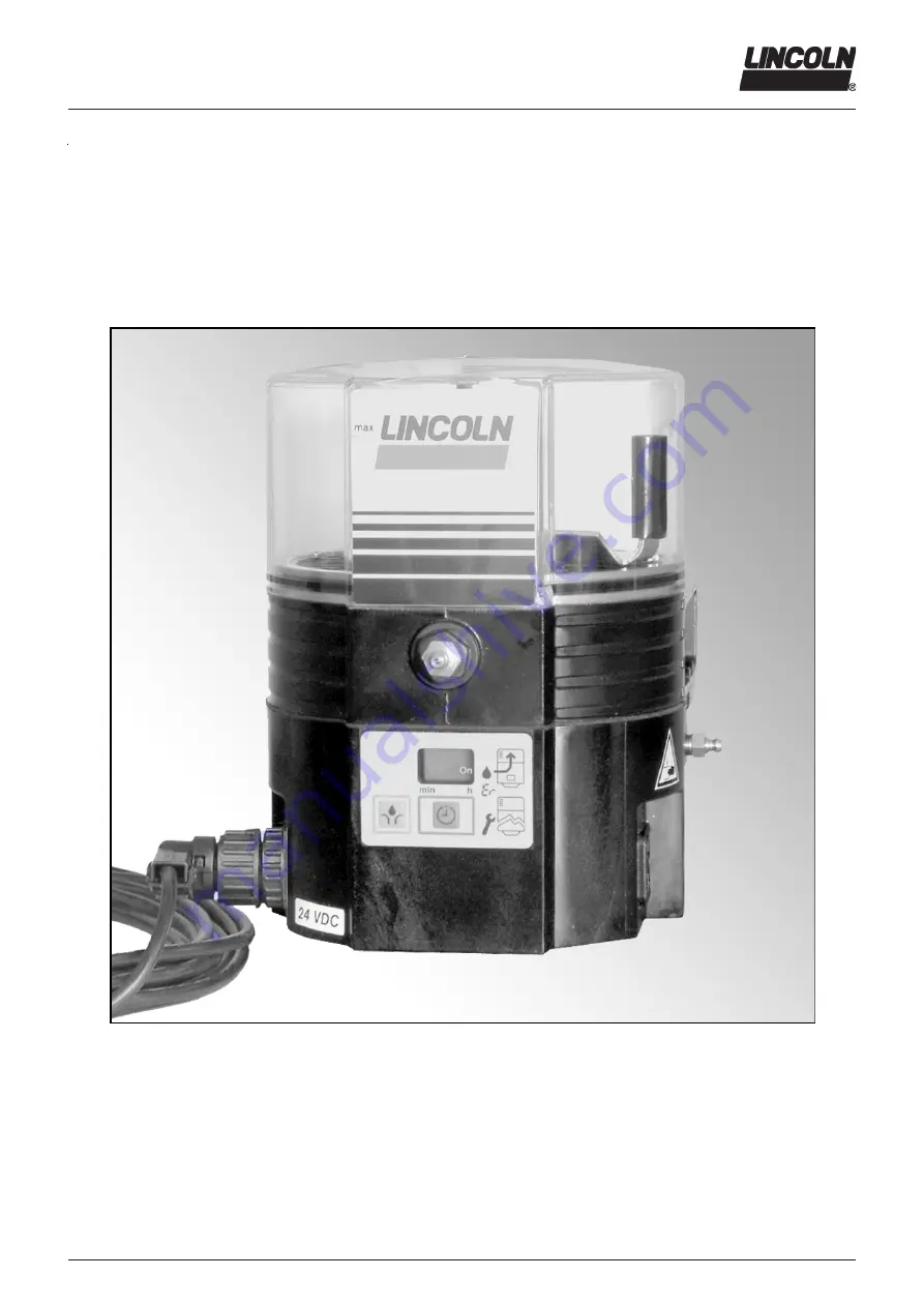
Lubrication System QLS 421
for Trailers and Semitrailers
B-Q42 1-000 a09
810-55405-1
Page 1: ...Subject to modificaitons User Manual InstallationandOperatingInstructions 2 1EN 38021 D09 Form 403013 Lubrication System QLS 421 for Trailers and Semitrailers B Q42 1 000 a09 810 55405 1...
Page 2: ...bH EdiDoc GmbH Heinrich Hertz Str 2 8 Erzberger Str 8 D 69169 Walldorf D 68753 Wagh usel All rights reserved Any duplication of this User Manual in its entirety or in part by whatever means is prohibi...
Page 3: ...Check valve 9 Direct internal feedback feature 10 Pumps with external metering device 10 Lubrication Points 10 Zerk Lock Connections 10 Connection of Feed Lines 11 First filling of a lubrication syst...
Page 4: ...cedural instruction User s Responsibility To ensure the safe operation of the unit the user is responsi ble for the following 1 The pump system shall be operated only for the in tended use see next ch...
Page 5: ...rong programming of the internal or external controller due to wrong planning and layout of the downstream lu bricant distribution caused by the use of contaminated lubricants due to the use of lubric...
Page 6: ...5 to connect pumps with direct current version in relation to the operating voltage acc to DIN 41755 Repair Repairs should only be performed by authorized personnel who are familiar with the repair in...
Page 7: ...urethane according to DIN VDE 0250 only use original Lincoln ADR tubes Certificate for QLS 421 ADR Berlin August 06 th 2007 QLS 421 Report 047 01 Component designation T EGG 047 01 For presentation at...
Page 8: ...vided into zones ac cording to the EX prescriptions These are the correspondences tank inside zone 0 fitting cabinet zone 1 shut off devices zone 1 venting devices zone 1 Zone 2 is located around zone...
Page 9: ...cant from a plugged outlet is redirected to the next outlet on the same side of the SSV divider block in de scending numerical order see fig 1 Example see fig 1 By closing of outlet 4 outlet 2 receive...
Page 10: ...reservoir The remaining outlets are to be used for the connection to the lube point or for increasing the lubricant quantity dou ble or triple comp fig 1 1 1013 A94 ATTENTION Do not plug outlets numbe...
Page 11: ...the moving parts of the machine that could damage the lubrication lines Mini mum bending radius is 50 mm 2 in Secure the lubrication lines to the machine using nylon ties clamps or straps provided in...
Page 12: ...output Electrical Connection Connect cables acc to connection diagram see chapter Technical Data 4273a 00 CAUTION Observe safety instructions in chapter Maintenance paragraph Electrical Connection Ins...
Page 13: ...o the threaded sleeve 1 1 Threaded sleeve 2 Main line 3 Hose stud Connection of the pressure plastic tube or the high pressure hose 10 09a98 Fig 5 2 Different types of check valves For high pressure h...
Page 14: ...kits see Technical Data Example of an explained model number Pump model P42131200531 grease pump SSV 6 divider block mounted on the back 24 VDC without low level and without dry contact with bayonet...
Page 15: ...lers and semi trailers do not have a permanent power supply The brake light voltage terminal 54 ren ders the power supply The operation dependent signal of terminal 15 ignition voltage as provided for...
Page 16: ...zes the times driven until then T1 TX When the vehicle moves on the pause time continues from where it had been interrupted when the vehicle had stopped Driving times are memorized until the adjusted...
Page 17: ...y reservoir LED display Er Fig 9 1 Precondition applied power supply power supply interrupted no segment or LED displayed Fig 9 2 blockage in the downstream system Fig 9 3 After refilling the lubrican...
Page 18: ...modifying the parameters in the pro gramming step Fig 9 1 Key for modifying Other functions In the operating mode Trigger additional lubrication In the programming mode Continuous activation Quick in...
Page 19: ...0 4 Display with segment for pause time The right hand segment On h indicates the available voltage supply during the pause time As soon as another message is displayed the segment turns off After the...
Page 20: ...bricating time after the pause time or in the case of an additional lubrication there exists a functional fault the control unit does not receive any feedback from the proximity switch After the monit...
Page 21: ...pletion of the programming check the parameter settings in the oper ating mode once again Operating Mode Display 42 79a00 4209a99 Fig 13 1 Starting operating mode Starting operating mode 6 001a02 IMPO...
Page 22: ...2 sec 42 83a00 42 84a00 Example 10 h 09 min rb 10 residual stand by time 10 hours after 2 sec 42 85a00 Fig 13 3 Display of parameters and states continuation next page 09 9 minutes Triggering an addi...
Page 23: ...ions EC 05 displayed as factor 1 Display after two sec 4278a0 0 after two sec after two sec 4297a00 4226a9 9 Fig 13 7 Display of manually triggered additional lubrications UC number of manually trigge...
Page 24: ...g paddle Fill the reservoir up to the Max mark via the filling nip ple 1 Fig 14 1 6001a02 IMPORTANT The grease must be free from impurities and must not be liable to change its consis tency in the cou...
Page 25: ...etering device via external or internal cycle switch Connect the electrical wires according to the following electrical connecting diagrams see chapter Technical Data Maintenance Repair and Tests cont...
Page 26: ...t the keypad is flashing Pump does not deliver lubricant an control pin at SSV metering device does not move Fill up the reservoir with clean lubricant Let the pump run initiate an additional operatin...
Page 27: ...ired for a full cycle of all metering devices Check pressure relief valve see chapter Operation Re place it if necessary A pressure relief valve B pump C SSV 12 metering device D feed lines R return l...
Page 28: ...A Electric data DC direct current Operating voltage 12 V 20 30 Operating current max 2 0 A Operating voltage 24 V 20 30 Operating current max 1 0 A Relay for malfunction DC 5 Malfunction Low level ind...
Page 29: ...eypad Technical Data continuation VDC connection diagram for mobile application with integrated control unit Type of connection 1A5 Bayonet plug DIN 72585 1 4 2 core X1 B Q421 050a 09 Connection diagr...
Page 30: ...r Manual InstallationandOperatingInstructions Subject to modificaitons Form 403013 Dimensions Pump 4234 d06 Rear mounted SSV metering device 4233a99 Number of outlets Dimensions A in mm 6 60 12 105 18...
Page 31: ...with the provisions of above mentioned directive Applied harmonized standards in particular Applied harmonized standards in particular DIN EN ISO Safety of machinery part 1 12100 1 Basic terminology...
Page 32: ...EN 38021 D09 Page 32 of 34 User Manual InstallationandOperatingInstructions Subject to modificaitons Form 403013 Service Parts Explosion view Connection Bayonet plug Type of connection 1A5 B Q421 0 60...
Page 33: ...element assy dia 6 mm x 1 650 28856 1 9 Sealing parts for pump element x 1 550 36979 5 10 Housing x 1 550 36981 3 11 Housing cover for VDC plug 1A1 0 x 1 550 34179 3 11 1 Socket with 6 m ca ble for Ba...
Page 34: ...tributers monitoring devices and accessories in stock and meet our exacting demands with their specialised knowledge about products installations and service Whenever and wherever you need our experts...