


Impinger X2 –Operator Manual
22
UTILITY SERVICE LAYOUT AND SECURING OVEN TO THE BASE
The lower oven must be securely mounted to the base using the
four (4)
base mounting plates (two plates if
model 3240) supplied by Lincoln. If a stack is installed, the top oven must also be secured to bottom oven.
Refer to
Figure C1
(page 24) for the location of utility connections and mounting plates for single ovens and
Figure C2
(page 25) for stack configurations.
SPACING
The right and back side of the oven must have a minimum 2 inch (50 mm) clearance from all surfaces. The
front of the oven requires a minimum of 36 inches (914.4mm) clearance from all surfaces. A minimum clearance
of 18” (457mm) on both sides of the oven may be required for service accessibility. In case other cooking
equipment is located on both sides of the oven, a minimum clearance of 24” (609mm) is required from that
equipment.
NOTE: Do not install this (these) oven(s) in any area with an ambient temperature in excess of
95
°
F
(35
°
C).
Doing so will cause damage to the unit(s).
CAUTION:
Oven(s) must be operated on approved bases only.
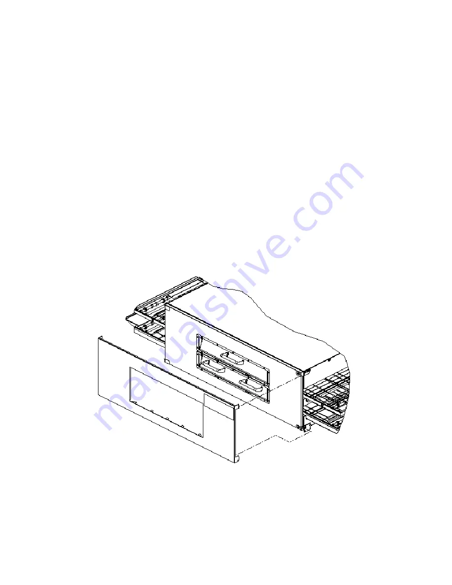
X2 HEAT SHIELD INSTALLATION
WITH THE RECOMMENDATION OF USING TWO PEOPLE,
PLACE HEAT SHIELD ON DOOR PINS BETWEEN DOOR SIDE
AND HINGE. UNLATCH ONE DOOR LATCH AT A TIME TO
SECURE THE HEAT SHIELD TO THE OVEN.
CAUTION: UNLATCHING BOTH LATCHES AT THE SAME TIME MAY CAUSE
DOOR TO FALL RESULTING IN BODILY INJURY.
Summary of Contents for Impinger 3262BWEC
Page 6: ...Impinger X2 Operator Manual 6...
Page 7: ...Impinger X2 Operator Manual 7...
Page 8: ...Impinger X2 Operator Manual 8 FIGURE A Rev 4 05...
Page 34: ...Impinger X2 Operator Manual 34 LABEL DEFINITIONS...
Page 41: ...9432 ELECTRIC UTILITY KIT UTILITY EXTENSION KIT INSTALLATION INSTRUCTIONS...
Page 46: ...This page intentionally left blank...
Page 52: ...Impinger X2 Operator Manual 52...


