background image

Retur

n to Section TOC

Retur

n to Section TOC

Retur

n to Section TOC

Retur

n to Section TOC

Retur

n to Master TOC

Retur

n to Master TOC

Retur

n to Master TOC

Retur

n to Master TOC

F-21

TROUBLESHOOTING & REPAIR

F-21

WIRE-MATIC 250

4.

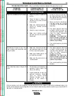
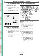
Test for 2 - 25 VDC between lead
#539 (positive) (8J5) and lead #541
(9J5) (negative) to determine if the
correct armature voltage is being
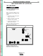
supplied.  See Figure F.8.

a.

Insert probes in to the Molex pin
cavities.

5.

Pull the gun trigger.

6.

Read meter.  Normal DC volts is
from 2 - 25 VDC.  VDC varies
depending on wire feed speed.

a.

If voltage to the wire drive motor
armature is zero, check the
wires between Plug J5 and the
wire drive motor.

b.

If the wires are okay and voltage
to the drive motor armature is
zero, the Control Board may be
faulty.  Replace. 

c.

If the correct DC armature volt-
age is present at the wire drive
motor, the motor or motor brush-
es may be faulty.  Test and/or
replace.

d.

If the motor is running at high
speed and the armature voltage
is high and uncontrollable, pro-
ceed with the tachometer test.

Test for Supply Voltage to
Tachometer

1.

Test for 15 VDC between lead
#515B (positive) (3J5) and lead
#206B (negative) (2J5) .  See Figure
F.8 for pin locations.

a.

Insert probes into Molex pin
cavities.

2.

Pull gun trigger.

3.

Read meter for 15 VDC.

a.

If the 15 VDC is present, check
the leads to the tach circuit.

b.

If the leads are okay and 15
VDC is present, the correct volt-
age is being received from the
Control Board.  Go to Feedback
Test.

c.

If the 15 VDC is not present and
the leads are okay, the Control
Board may be faulty.  Replace.

Test for Feedback Voltage to the
Control Board

1.

Test for 1.5 - 3.5 VDC between lead
#555 (positive) (1J5) and lead
#206B (negative) (2J5) .  See Figure
F.8 for pin locations.

a.

Insert probes into Molex pin
cavities.

2.

Pull gun trigger.

3.

Read meter for 1.5 - 3.5 VDC.

a.

If the 1.5 - 3.5 VDC is present,
the tach circuit is sending the
correct feedback signal to the
Control Board.

NOTE:  IF THE MOTOR IS NOT RUN-
NING, THE FEEDBACK VOLTAGE MAY
BE FROM 0 TO 5 VDC.

b.

If the 1.5 - 3.5 VDC is not pre-
sent or not correct, the Control
Board is not receiving the prop-
er feedback voltage from the
tach circuit.  Check the leads
from the tach circuit to the
Control Board for loose or bro-
ken connections.

c.

If the leads are okay, the Control
Board may be faulty.  Replace.

WIRE DRIVE MOTOR AND TACHOMETER FEEDBACK TEST (CONTINUED)

Summary of Contents for WIRE-MATIC 250

Page 1: ... can be increased by proper installation and thoughtful operation on your part DO NOT INSTALL OPERATE OR REPAIR THIS EQUIPMENT WITHOUT READ ING THIS MANUAL AND THE SAFETY PRECAUTIONS CON TAINED THROUGHOUT And most importantly think before you act and be careful For use with machines having Code Numbers WIRE MATIC 250 20 18 16 14 22 24 26 28 VOLTS 300 250 200 150 350 400 450 500 WIRE SPEED 100 550 ...

Page 2: ...ol 1 c In semiautomatic or automatic wire welding the electrode electrode reel welding head nozzle or semiautomatic welding gun are also electrically hot 1 d Always be sure the work cable makes a good electrical connection with the metal being welded The connection should be as close as possible to the area being welded 1 e Ground the work or metal to be welded to a good electrical earth ground 1 ...

Page 3: ...ing area If this is not possible cover them to prevent the welding sparks from starting a fire Remember that welding sparks and hot materials from welding can easily go through small cracks and openings to adjacent areas Avoid welding near hydraulic lines Have a fire extinguisher readily available 4 b Where compressed gases are to be used at the job site special precautions should be used to preve...

Page 4: ...ell ventilated areas or vent the engine exhaust fumes outdoors ____________________________________________________ 7 c Do not add the fuel near an open flame welding arc or when the engine is run ning Stop the engine and allow it to cool before refueling to prevent spilled fuel from vaporizing on contact with hot engine parts and igniting Do not spill fuel when filling tank If fuel is spilled wip...

Page 5: ... à proximité au soudage à l aide d écrans appropriés et non inflammables 4 Des gouttes de laitier en fusion sont émises de l arc de soudage Se protéger avec des vêtements de protection libres de l huile tels que les gants en cuir chemise épaisse pan talons sans revers et chaussures montantes 5 Toujours porter des lunettes de sécurité dans la zone de soudage Utiliser des lunettes avec écrans latera...

Page 6: ...NOTES WIRE MATIC 250 Return to Master TOC Return to Master TOC Return to Master TOC Return to Master TOC ...

Page 7: ...Kit C 1 Making a Weld with the Spool Gun Adapter K607 1 Installed C 5 Timer Kit K585 1 C 6 Timer Kit Installation Optional K585 1 C 6 Making Spot and Stitch Welds with Timer Kit Installed C 7 Adjustable Gas Regulator and Hose Kit K586 1 C 7 Drive Roll Kits C 7 Maintenance Section D Safety Precautions D 1 Routine and Periodic Maintenance D 1 Drive Rolls and Guide Tubes D 3 Drop In Reel Spindle and ...

Page 8: ...al Protection E 5 SCR Operation E 6 Troubleshooting and Repair Section F How to use Troubleshooting Guide F 1 PC Board Troubleshooting Procedures F 2 Troubleshooting Guide F 3 Test Procedures F 10 Oscilloscope Waveforms F 22 Replacement Procedures F 27 Electrical Diagrams Section G Parts List P 218 TABLE OF CONTENTS continued Page vi WIRE MATIC 250 ...

Page 9: ...ation A 2 Stacking A 2 Tilting A 2 Input Connections A 2 Fuse and Wire Sizes A 3 Input Power Connections and Ground Connections A 3 Connect Shielding Gas A 4 Reconnect Procedure A 5 Connect Output Components A 7 Install the Work Clamp A 7 Output Polarity Connection A 7 Gun Liner and Contact Tip Installation A 7 Wire Size Conversion Parts A 8 Gun and Cable Installation A 8 TABLE OF CONTENTS INSTALL...

Page 10: ...r Breaker Size Copper conduit AWG Ground Wire in Conduit IEC Sizes Runs to Runs over 100ft 30m 100ft 30m 208 60 60 8 10mm2 6 16mm2 10 6mm2 230 60 60 10 6mm2 8 10mm2 10 6mm2 460 60 30 14 2 5mm2 12 4mm2 10 6mm2 575 60 25 14 2 5mm2 12 4mm2 10 6mm2 HEIGHT Width DEPTH WEIGHT W GUN 28 2 18 8 40 1 220 lbs 719mm 480mm 1019mm 100 Kg Standard Voltage Input Current at Rated Output 208 230 1 60 53 49 Amps 230...

Page 11: ...n a stable level surface so it will not topple over Do not place the machine on an incline A 2 INSTALLATION WIRE MATIC 250 A 2 INPUT CONNECTIONS All input power must be electrically disconnected before proceeding ____________________________________ 1 Before starting the installation check with the local power company to determine if there is any ques tion about whether your power supply is adequa...

Page 12: ...t input cord and plug connected to the welder mount the matching receptacle supplied with the machine 1 Mount the receptacle in a suitable location using the screws provided 2 Locate the receptacle within reach of the 10 ft input cord attached to the welder 3 Mount the receptacle with the grounding terminal at the top This allows the power cable to hang down without bending See Figure A 2 a The ce...

Page 13: ... Argon blend gas the optional K586 1 Adjustable Gas Regulator and Hose Kit should be used See Accessories Section of this manual Gas under pressure is explosive Always keep gas cylinders in an upright position and always keep chained to undercarriage or sta tionary Y support See American National Standard Z 49 1 Safety in Welding and Cutting published by the American Welding Society ______________...

Page 14: ...fraction of a turn a When the cylinder pressure gage pointer stops moving open the valve fully NEVER STAND DIRECTLY IN FRONT OF OR BEHIND THE FLOW REGULATOR WHEN OPENING THE CYLINDER VALVE ALWAYS STAND TO ONE SIDE NOTE The Optional K586 1 flow regulator is adjustable Adjust the flow regulator for the flow rate recommended for the procedure and process being used before making the weld FIGURE A 4 I...

Page 15: ...MER INPUT LEAD IS CONNECTED 2 SHIFT THE TRANSFORMER INPUT LEAD TO THE TERMINAL THAT THE UNIT IS TO OPERATE ON AND FASTEN SECURELY WITH THE HEX NUT REMOVED IN STEP1 MAKE CERTAIN THAT BRASS NUTS ARE TIGHT 1 ALL MACHINES ARE SHIPPED FROM THE FACTORY CONNECTED FOR THE HIGHEST NAME PLATED SINGLE PHASE INPUT VOLTAGE TO CHANGE CONNECTIONS FOR A DIFFERENT INPUT VOLTAGE RECONNECT BOTH COPPER JUMPERS PER DI...

Page 16: ... the gun connector The positive lead is stamped on its ter minal and should be reconnected to the work lead ter minal A 7 INSTALLATION WIRE MATIC 250 A 7 GUN LINER AND CONTACT TIP INSTALLATION The Magnum 250L gun and cable provided with the WIRE MATIC 250 is factory installed with a liner for a 035 045 0 9 1 2mm diameter electrode and an 035 0 9mm contact tip 1 If a 045 diameter wire size is to be...

Page 17: ...nnect the gun trigger connector from the gun and cable to the mating receptacle on the front panel Make sure that the keyways are aligned insert and tighten retaining ring NOTE If a gun and cable other than the Magnum 250L is used it must conform to connector specifica tions and the gun trigger switch must be capable of switching 5 milliamps at 15 volts DC resistive The gun trigger switch connecte...

Page 18: ...NOTES WIRE MATIC 250 Return to Section TOC Return to Section TOC Return to Section TOC Return to Section TOC Return to Master TOC Return to Master TOC Return to Master TOC Return to Master TOC ...

Page 19: ...res B 2 Power Source Features B 2 Wire Feeder Features B 3 Machine Capability B 3 Limitations B 3 Controls and Settings B 4 Using the Wire Drive Roll B 5 Procedure for Changing Drive Roll B 5 Loading the Wire Reel B 5 Feeding Electrode B 6 Proper Wire Feeding B 6 Setting Idle Roll Pressure B 7 Operating Steps B 7 Starting the Welder B 7 Changing Run In Mode B 7 Enter Fast Run In Mode B 7 Enter Slo...

Page 20: ...rm a reliable high performance welding system Simple controls consisting of continuous full range cal ibrated voltage control and wire feed speed control provide versatility with ease of use WIRE MATIC 250 WARNING FUMES AND GASES can be dangerous Keep your head out of fumes Use ventilation or exhaust to remove fumes from breathing zone ARC RAYS can burn Wear eye ear and body protection WELDING CUT...

Page 21: ... to 30 lb 4 5 to 13 6 kg 2 51mm I D spools or Readi Reel coils with optional adapter of 025 through 045 0 6 1 2mm solid steel 035 0 9mm stainless steel 3 64 1 2mm aluminum 045 1 2mm Outershield 035 0 9mm and 045 1 2mm Innershield self shielding electrodes The WIRE MATIC 250 is factory equipped to feed 035 0 9mm and 045 1 2mm electrodes It includes a 12 ft 3 6m GMAW gun and cable assem bly equipped...

Page 22: ...ger to resume welding once the overload condition has been cleared Unique Drive Roll and Guide Tube Design Precisely aligned guide tubes and drive rolls provide long life The design also permits quick reload by sim ply starting wire into ingoing guide tube Adjustable tension setting minimizes birdnesting eliminates milling through the wire and gives positive feeding The double groove reversible dr...

Page 23: ...KNOB Controls the wire speed from 50 to 600 inches per minute 1 2 to 15 2 m min The control can be preset on the dial to the setting specified on the Procedure Decal on the inside of the wire com partment door Wire speed is not affected when changes are made in the voltage control NOTE When the trigger is pulled the wire feeder feeds wire at low speed regardless of the wire feed speed set on the c...

Page 24: ...the gun liner and contact tip are prop erly sized for wire being used LOADING THE WIRE REEL To mount a 22 30 lb 10 14 kg Readi Reel package using the optional Readi Reel Adapter K363P 1 Pull the spindle up out of the WIRE MATIC 250 spindle mounting clips V brackets 2 Snap the spindle into the Readi Reel adapter so the spindle drive pin is engaged with the hole pro vided in the Adapter 3 Rotate the...

Page 25: ...ize and type are being used 1 Turn the Readi Reel or spool until the free end of the electrode is accessible 2 Tightly holding the electrode cut off the bent end and straighten the first six inches a If the electrode is not properly straightened it may not feed properly into the outgoing guide tube or welding gun causing a birdnest 3 Cut off the first inch 4 Push the wire through the ingoing guide...

Page 26: ...e feeder motor NOTE When the POWER SWITCH is ON the fan motor is thermostatically controlled to provide cooling for the transformer and other components only when the machine needs cooling When the machine does not require fan cooling the fan does not run such as when first turned on when welding at low current or at low duty cycle procedures CHANGING RUN IN MODE Later models only The WIRE MATIC 2...

Page 27: ...proximately 3 8 10mm of the end of the contact tip or 3 4 20mm for Outershields NOTE When the trigger is pulled the wire feeder feeds wire at low speed regardless of the set wire feed speed until the welding arc starts or 2 seconds has elapsed This feature enhances starting and makes it easier to set the stickout The 2 second limit permits high speed loading of the gun and cable To change run in m...

Page 28: ...NOTES WIRE MATIC 250 Return to Section TOC Return to Section TOC Return to Section TOC Return to Section TOC Return to Master TOC Return to Master TOC Return to Master TOC Return to Master TOC ...

Page 29: ...1 Spool Adapter Kit C 1 Spool Gun Module Board Installation C 2 Spool Gun Connection Box Installation C 3 Spool Gun Preparation C 4 Spool Gun Connection C 4 Making a Weld with the Spool Gun Adapter K607 1 Installed C 5 Timer Kit K585 1 C 6 Timer Kit Installation Optional K585 1 C 6 Making Spot and Stitch Welds with Timer Kit Installed C 7 Adjustable Gas Regulator and Hose Kit K586 1 C 7 Drive Roll...

Page 30: ...ts inside the control sec tion of the machine It provides control and inter con nection between the machine s control board and the spool gun kit connection box The connection box mounts to the front of the machine s base It provides for inlet connection of the OPTIONS ACCESSORIES REPLACEMENT MAGNUM 250L GUN AND CABLE ASSEMBLY The following GMAW gun and cable assemblies are available for use with ...

Page 31: ...sition the Spool Gun Module Board over the snap mount fasteners with the lead plug connec tors at the top 6 Gently press the board onto the fasteners making sure all the fasteners snap into place 7 Remove the hex head screw from beneath the gas connector on the wire drive side of the machine to release the small metal cover See Figure C 2 FIGURE C 2 Spool Gun Installation 8 Slide the metal cover o...

Page 32: ...Case into the slots in the base Make sure the lip of the case side is lifted over the top edge of the center panel during installation a Fasten Case Side with the six screws removed SPOOL GUN CONNECTION BOX INSTALLATION NOTE Model codes below 9900 require the addition of three holes to the front of the machine s base as shown in Figure C 3 FIGURE C 3 Spool Gun Connection Box Installation Mounting ...

Page 33: ... and tighten the set screw for a positive electrical connection 4 Pull the rubber boot over the plug to insulate the connection SPOOL GUN CONNECTION The spool gun module is intended for use with Lincoln Electric Magnum Spool Guns only Use with other units may cause damage to the equip ment For Spool Gun operation refer to the instruction manual provided with the Magnum Spool Gun __________________...

Page 34: ...T and activates Spool Gun gas out put MAKING THE WELD 1 Set the transfer switch in the SPOOL GUN posi tion 2 Turn input power ON by setting the POWER SWITCH in the ON position 3 Adjust the VOLTAGE CONTROL KNOB to increase or decrease your welding Voltage 4 Adjusting the Wire Speed Control will increase or decrease the Spool Gun Wire Feed Speed This represents the set speed for the K469 Spool Gun a...

Page 35: ...___________________ 1 Verify that the following items have been included in the kit a Timer Board and Panel Assembly b Two sheet metal screws c Wiring harness 2 Turn the POWER SWITCH to OFF 3 Disconnect AC input power to the machine 4 Remove the Cover Plate Assembly from the front of the machine by removing the two screws which fasten it using a screwdriver a 5 16 8mm nut dri ver or other suitable...

Page 36: ...T STITCH ON TIME KNOB sets welding time a Start with a dial setting of 0 5 seconds Raise setting to increase penetration and weld size Lower setting to reduce burnthrough and dis tortion 2 The STITCH OFF TIME KNOB sets off time between welds a Start with a dial setting of 0 5 seconds Raise setting to reduce burnthrough Lower setting to make weld flatter and smoother 3 Set the procedure for the met...

Page 37: ... D 2 Drive Rolls and Guide Tubes D 3 Drop In Reel Spindle and Clips D 3 Cable Cleaning D 3 Gun Tubes and Nozzles D 3 Contact Tip and Gas Nozzle Installation D 3 Liner Removal and Replacement D 4 Liner Removal Installation and Trimming Instructions for Magnum 250L D 4 Gun Handle Disassembly D 5 Accessories and Expendable Replacement Parts for Magnum 250L Gun and Cable Assemblies D 6 TABLE OF CONTEN...

Page 38: ...e materials are in the welding or cutting area or around the machine 2 Remove any debris dust dirt or materials that could block the air flow to the machine 3 Inspect the electrode cables for any slits punc tures in the cable jacket or any condition that would affect the proper operation of the machine Perform Periodically Clean the inside of the machine with low pressure air stream Clean the foll...

Page 39: ...TOC Return to Section TOC Return to Section TOC Return to Section TOC Return to Master TOC Return to Master TOC Return to Master TOC Return to Master TOC D 2 MAINTENANCE D 2 Figure D 1 Component Locations WIRE MATIC 250 ...

Page 40: ... a plug ____________________________________ 4 Flex the cable over its entire length and again blow out the cable 5 Repeat this procedure until no more dirt comes out GUN TUBES AND NOZZLES 1 Replace worn contact tips as required 2 Remove spatter from the inside of the gas nozzle and tip every 10 minutes of arc time or as required CONTACT TIP AND GAS NOZZLE INSTALLATION 1 Choose the correct size co...

Page 41: ...w located in the brass connec tor at the feeder end of the cable and pull the liner out of the cable 7 Insert a new untrimmed liner into the connector end of the cable a Check the liner bushing stencil to make sure it is the appropriate one for the wire size being used 8 Fully seat the liner bushing into the connector 9 Tighten the setscrew on the brass cable connector NOTE Do not install the gas ...

Page 42: ...ted or serviced if necessary The gun handle consists of two halves that are held together with a collar on each end To open up the handle 1 Turn the collars approximately 60 degrees coun terclockwise the same direction as removing a right hand thread until the collar reaches a stop 2 Pull the collar off the gun handle NOTE If the collars are difficult to turn position the gun handle against a corn...

Page 43: ...Wire 0 6 mm 0 8 mm 0 9 mm 1 2 mm 0 9 mm 1 2 mm 0 6 mm 0 8 mm 0 9 mm 1 2 mm 0 6 0 8 mm 0 9 1 2 mm 12 7 mm 15 9 mm ENGLISH SIZE 025 030 035 045 3 64 Alum Wire 025 030 035 045 035 045 025 030 035 045 0 25 030 0 35 045 1 2 5 8 PART NO M16087 2 M16087 1 M17701 1 S19391 6 S19391 7 S19391 1 S19391 2 S19392 1 S19292 2 S19393 5 S19393 6 S19393 1 S19393 2 S19418 2 S19418 1 M16093 2 M16093 1 S19417 1 M16938 ...

Page 44: ...NOTES WIRE MATIC 250 Return to Section TOC Return to Section TOC Return to Section TOC Return to Section TOC Return to Master TOC Return to Master TOC Return to Master TOC Return to Master TOC ...

Page 45: ...ltage and Main Transformer E 1 Output Rectification and Feedback Control E 2 Constant Voltage Output E 3 Wire Drive Motor and Feedback E 4 Thermal Protection E 5 SCR Operation E 6 TABLE OF CONTENTS THEORY OF OPERATION SECTION LINE SWITCH MAIN TRANSFORMER RECONNECT FAN MOTORS SCR RECTIFIER C A P A C I T O R S SHUNT CHOKE WIRE DRIVE MOTOR TACH POSITIVE TERMINAL NEGATIVE TERMINAL GAS SOLENOID WIRE SP...

Page 46: ...ary winding that sup plies power to the Control Board for SCR gate drive and gas solenoid operation The weld power windings connect to the Control Board as well as to the main SCR Rectifier Figure E 2 Input Line Voltage and Main Transformer INPUT LINE VOLTAGE AND MAIN TRANSFORMER LINE SWITCH MAIN TRANSFORMER RECONNECT FAN MOTORS SCR RECTIFIER C A P A C I T O R S SHUNT CHOKE WIRE DRIVE MOTOR TACH P...

Page 47: ...he firing of the SCRs thus con trolling the output of the machine See SCR Operation The control board also powers and com mands the gas solenoid and the wire drive motor Figure E 3 Output Rectification and Feedback OUTPUT RECTIFICATION AND FEEDBACK LINE SWITCH MAIN TRANSFORMER RECONNECT FAN MOTORS SCR RECTIFIER C A P A C I T O R S SHUNT CHOKE WIRE DRIVE MOTOR TACH POSITIVE TERMINAL NEGATIVE TERMIN...

Page 48: ...of the machine Figure E 4 Constant Voltage Output CONSTANT VOLTAGE OUTPUT LINE SWITCH MAIN TRANSFORMER RECONNECT FAN MOTORS SCR RECTIFIER C A P A C I T O R S SHUNT CHOKE WIRE DRIVE MOTOR TACH POSITIVE TERMINAL NEGATIVE TERMINAL GAS SOLENOID WIRE SPEED ARC VOLTAGE CONTROL BOARD FEEDBACK GUN TRIGGER AND THUMB SWITCH F E E D B A C K G A T E I G N S A L NOTE Unshaded areas of Block Logic Diagram are t...

Page 49: ... turn regulates the electrode wire feed speed through the gun Figure E 5 Wire Drive Motor and Feedback WIRE DRIVE MOTOR AND FEEDBACK LINE SWITCH MAIN TRANSFORMER RECONNECT FAN MOTORS SCR RECTIFIER C A P A C I T O R S SHUNT CHOKE WIRE DRIVE MOTOR TACH POSITIVE TERMINAL NEGATIVE TERMINAL GAS SOLENOID WIRE SPEED ARC VOLTAGE CONTROL BOARD FEEDBACK GUN TRIGGER AND THUMB SWITCH F E E D B A C K G A T E I...

Page 50: ...e cooling fan motors when required The other choke thermostat opens the trigger circuit preventing machine weld output and wire feed if excessive operating temperatures are detected The third thermostat insures that the fan motors are operating when required The thermostats are self resetting once the machine cools sufficiently If the thermostat shutdown is caused by excessive output or duty cycle...

Page 51: ...plied to the SCR the device spends a certain portion of the AC cycle time in the off state and the remainder of the time in the on state The amount of time spent in the ON state is con trolled by the gate An SCR is fired by a short burst of current into the gate This gate pulse must be more positive than the cath ode voltage Since there is a standard PN junction between gate and cathode the voltag...

Page 52: ...Return to Section TOC Return to Section TOC Return to Section TOC Return to Section TOC Return to Master TOC Return to Master TOC Return to Master TOC Return to Master TOC NOTES WIRE MATIC 250 ...

Page 53: ... Normal Open Circuit Voltage Waveform F 22 Typical Output Voltage Waveform Machine Loaded F 23 Abnormal Output Voltage Waveform Machine Loaded One Output SCR Not Functioning F 24 Abnormal Open Circuit Voltage Output Capacitor Bank Not Functioning F 25 Typical SCR Gate Voltage Waveform F 26 Replacement Procedures Control PC Board Removal and Replacement F 27 Wire Drive Assembly Removal and Replacem...

Page 54: ...ct com ponent is either good or bad If there are a number of possible components check the components in the order listed to eliminate one possibility at a time until you locate the cause of your problem All of the referenced test procedures referred to in the Troubleshooting Guide are described in detail at the end of this chapter Refer to the Troubleshooting and Repair Table of Contents to locat...

Page 55: ...ing on equipment Do not touch electrically hot parts Remove the P C Board from the static shielding bag and place it directly into the equipment Don t set the P C Board on or near paper plastic or cloth which could have a static charge If the P C Board can t be installed immediately put it back in the static shielding bag If the P C Board uses protective shorting jumpers don t remove them until in...

Page 56: ...oln Electric Service Dept 216 383 2531 or 1 800 833 9353 WELD 1 Check input power switch S1 It may be faulty 2 Check for lose or broken wires at the reconnect panel 3 Perform Main Transformer Test 4 Check the thermostats and associated leads for loose or broken connections See wiring diagram 5 The control board may be faulty Replace 1 Contact your local Lincoln Electric Authorized Field Service Fa...

Page 57: ...erform the SCR Rectifier Assembly Test 4 The control board may be faulty Replace 1 Check for loose or faulty con nections of the heavy current carrying leads 2 The output capacitor bank may be faulty Check for loose con nections at the capacitors Also check for leaky capacitors Replace if necessary WARNING The liquid elec trolyte in these capacitors is toxic Avoid contact with any portion of your ...

Page 58: ...tinuously or pulsing when gun trigger is NOT activated 1 Check the machine s internal trigger leads for grounds or shorts See Wiring Diagram 2 The control board may be faulty Replace 1 Remove the gun If the problem is resolved the gun trigger circuit is faulty Repair or replace 2 If the problem is not resolved then contact your Local Lincoln Electric Authorized Field Service Facility If for any re...

Page 59: ...e control board Plug J8 and applying a 12 VDC external supply to the gas solenoid If the solenoid does NOT activate then it may be faulty Replace 2 The control broad may be faulty Replace 1 Check the motor armature cur rent Normal armature current is 1 75 amps maximum If the motor armature current is normal the control board may be faulty Replace 2 If the motor armature current is high 2 to 2 5 am...

Page 60: ...ch Feedback test 3 The control board may be faulty Replace 1 Perform the Wire Drive Motor and Tach Feedback Test 2 The Wire Feed Control poten tiometer may be faulty Check or replace See Wiring Diagram 3 The control board may be faulty Replace 1 The wire feed speed control may be dirty Rotate several times and check if problem is resolved 1 If the drive rolls are turning then check for a mechanica...

Page 61: ...lace 1 The output capacitor bank may be faulty Check for loose con nections at the capacitors Also check for leaky capacitors Replace if necessary WARNING The liquid elec trolyte in these capacitors is toxic Avoid contact with any portion of your body 2 The control board may be faulty Replace 1 Check for worn or melted con tact tip 2 Check for loose or faulty con nections on the work and elec trod...

Page 62: ...r Bridge Test 2 The control board may be faulty Replace 1 The control board may be faulty Replace 1 Check the welding cable con nections for loose or faulty con nections 2 Make sure the wire feed speed voltage and shielding gas are correct for the process being used 1 Check the welding cable con nections for loose or faulty con nections 2 Make sure the wire feed speed voltage and shielding gas are...

Page 63: ...Service and repair should be performed only by Lincoln Electric factory trained per sonnel Unauthorized repairs performed on this equipment could result in danger to the technician or the machine operator and will invalidate your factory warranty For your safety and to avoid electrical shock please observe all safety notes and pre cautions detailed throughout this manual If for any reason you do n...

Page 64: ...ts __________________________ NOTE Secondary voltages will vary proportionably with the primary input voltage 1 Disconnect the main input power supply to the machine 2 Remove the Case Top and Side Panels with a 5 16 nut driver 3 Locate Plug J3 and Plug J6 on the G2332 Control PC Board NOTE The location of Plugs may vary depending on the machine code FIGURE F 1 G2332 Control PC Board Main Transform...

Page 65: ...tween the reconnect panel and the ON OFF POWER SWITCH test the ON OFF POWER SWITCH for proper operation b If the correct nameplate voltage is being applied to the main transformer and one or more of the secondary voltages are missing or are incorrect the main transformer may be faulty Replace 4 Locate the following leads on Plug J3 G2332 5 Connect main input power to the machine 6 Turn the Wire Ma...

Page 66: ...d or socket wrench STATIC SCR RECTIFIER ASSEMBLY TEST Service and repair should be performed only by Lincoln Electric factory trained per sonnel Unauthorized repairs performed on this equipment could result in danger to the technician or the machine operator and will invalidate your factory warranty For your safety and to avoid electrical shock please observe all safety notes and pre cautions deta...

Page 67: ...ly isolates the SCR bridge assembly See Figure F 2 FIGURE F 2 Remove Plugs J3 and J6 to Perform Static SCR Rectifier Assembly Test 3 Verify that the capacitors have com pletely discharged with an Analog Volt Ohm meter 4 Disconnect leads X2 and X3 from the negative capacitor bank using a 1 2 open end wrench See Figure F 3 FIGURE F 3 Location of Leads X2 and X3 5 Separate leads X2 and X3 from the ne...

Page 68: ...hode of SCR 1 See Figure F 4 Use an analog ohmmeter Multimeter FIGURE F 4 SCR 1 Test Points 7 Test for high or infinite resistance from the cathode to the anode of SCR 1 by reversing the meter leads See Figure F 4 a If a high or infinite resistance is indicated for both tests 6 and 7 the SCR 1 is not shorted b If a low resistance is indicated in either tests 6 or 7 the SCR is faulty Replace SCR As...

Page 69: ...R Heat Sink Assembly Drawings Service and repair should be performed only by Lincoln Electric factory trained per sonnel Unauthorized repairs performed on this equipment could result in danger to the technician or the machine operator and will invalidate your factory warranty For your safety and to avoid electrical shock please observe all safety notes and pre cautions detailed throughout this man...

Page 70: ...e capacitor bank using a 1 2 open end wrench See Figure F 6 FIGURE F 6 Location of Leads X2 and X3 5 Separate leads X2 and X3 from the negative capacitor bank buss bar Be sure there is no electrical con tact See Figure F 6 NOTE DO NOT DISASSEMBLE THE SCR RECTIFIER HEAT SINK ASSEM BLY 6 Construct the circuit shown in Figure F 7 One 6 volt lantern battery can be used R1 and R2 resistor values are 10...

Page 71: ... closed and after the switch is open the SCR is functioning b If the voltages is 3 6 volts only when the switch is closed or there is no voltage when the switch is closed the SCR is defective NOTE Be sure battery is functioning properly A low battery can affect the results of the test Repeat Battery Test Procedure in Step 6 if needed 12 Open switch SW 1 13 Reconnect the Tester leads See Figure F 7...

Page 72: ...er sonnel Unauthorized repairs performed on this equipment could result in danger to the technician or the machine operator and will invalidate your factory warranty For your safety and to avoid electrical shock please observe all safety notes and pre cautions detailed throughout this manual If for any reason you do not understand the test procedures or are unable to perform the tests repairs safe...

Page 73: ... BE OBSERVED FOR THESE TESTS Test for Correct Wire Drive Motor Armature Voltage 1 Disconnect main input power to the machine 2 Remove the Case Top and Side Panels using a 5 16 nut driver 3 Locate Plug J5 on the G2332 Control Board See Figure F 8 FIGURE F 8 Plug J5 Location on G2332 PC Control Board WIRE DRIVE MOTOR AND TACHOMETER FEEDBACK TEST CONTINUED G2332 WM 250 CONTROL J2 J7 J4 J10 J6 J9 J3 J...

Page 74: ...t for 15 VDC between lead 515B positive 3J5 and lead 206B negative 2J5 See Figure F 8 for pin locations a Insert probes into Molex pin cavities 2 Pull gun trigger 3 Read meter for 15 VDC a If the 15 VDC is present check the leads to the tach circuit b If the leads are okay and 15 VDC is present the correct volt age is being received from the Control Board Go to Feedback Test c If the 15 VDC is not...

Page 75: ...is is a typical DC output voltage wave form generated from a properly operating machine Note that each vertical division represents 20 volts and that each horizontal division represents 2 milliseconds in time Note Scope probes connected at machine output terminals probe to electrode probe to work Volts Div 20 V Div Horizontal Sweep 2 ms Div Coupling DC Trigger Internal SCOPE SETTINGS NORMAL OPEN C...

Page 76: ...ated from a properly operating machine Note that each vertical division represents 20 volts and that each horizontal division represents 5 milliseconds in time The machine was loaded with a resistance grid bank Note Scope probes connected at machine output terminals probe to electrode probe to work Volts Div 20 V Div Horizontal Sweep 5 ms Div Coupling DC Trigger Internal SCOPE SETTINGS MACHINE LOA...

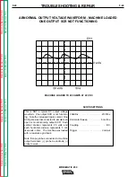
Page 77: ...ent One SCR gate was disconnected to simulate an open or non functioning output SCR Each vertical division represents 20 volts and each horizontal division represents 5 mil liseconds in time The machine was loaded with a resistance grid bank Note Scope probes connected at machine output terminals probe to electrode probe to work Volts Div 20 V Div Horizontal Sweep 5 ms Div Coupling DC Trigger Inte...

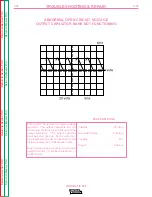
Page 78: ...put capacitors are not functioning Note the lack of filtering in the output waveform The output capacitor bank was disconnected Each vertical divi sion represents 20 volts and each horizontal division represents 5 milliseconds in time Note Scope probes connected at machine output terminals probe to electrode probe to work Volts Div 20 V Div Horizontal Sweep 5 ms Div Coupling DC Trigger Internal SC...

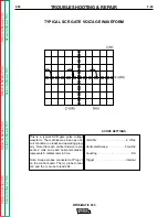
Page 79: ...e pulse voltage waveform The machine was in an open cir cuit condition no load and operating prop erly Note that each vertical division repre sents 2 volts and each horizontal division represents 5 milliseconds in time Note Scope probes connected at Plug J3 on the control board The probe to lead G2 and the probe to lead 204 Volts Div 2 V Div Horizontal Sweep 5 ms Div Coupling DC Trigger Internal S...

Page 80: ...ory trained per sonnel Unauthorized repairs performed on this equipment could result in danger to the technician or the machine operator and will invalidate your factory warranty For your safety and to avoid electrical shock please observe all safety notes and pre cautions detailed throughout this manual If for any reason you do not understand the test procedures or are unable to perform the tests...

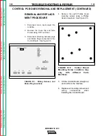
Page 81: ...ay vary with different Code Machines 5 Lift the Control Board straight up and out from the machine 6 Replace all mounting screws and wiring connections when installing the Control Board CONTROL PC BOARD REMOVAL AND REPLACEMENT CONTINUED REMOVAL AND REPLACE MENT PROCEDURE 1 Disconnect main input power the machine 2 Remove the Case Top and Side Panels using 5 16 nut driver 3 Disconnect all wiring ha...

Page 82: ...rained per sonnel Unauthorized repairs performed on this equipment could result in danger to the technician or the machine operator and will invalidate your factory warranty For your safety and to avoid electrical shock please observe all safety notes and pre cautions detailed throughout this manual If for any reason you do not understand the test procedures or are unable to perform the tests repa...

Page 83: ...rewdriver located in front of the drive roll See Figure F 11 a Note the placement of the insu lators and washers for replace ment FIGURE F 11 Wire Drive Assembly Removal 4 Using a small slot head screw driver loosen the set screw holding the out going guide tube into the drive roll assembly Carefully slide out the wire drive assembly 5 Disconnect the six pin plug from the vertical baffle connector...

Page 84: ...ly by Lincoln Electric factory trained per sonnel Unauthorized repairs performed on this equipment could result in danger to the technician or the machine operator and will invalidate your factory warranty For your safety and to avoid electrical shock please observe all safety notes and pre cautions detailed throughout this manual If for any reason you do not understand the test procedures or are ...

Page 85: ...achine using a slot head screwdriver and 3 8 open end wrench FIGURE F 13 Heat Sink lead discon nection 4 Cut the SCR gate leads G1 and G2 see wire markers and wiring dia gram using wire cutters a The easiest access to these leads is from the right side of the machine b Cut any necessary cable ties 5 Remove the four screws holding the SCR Assembly to the floor of the machine using a 5 16 nut driver...

Page 86: ...APACITOR BANK REMOVAL AND REPLACEMENT WARNING Service and repair should be performed only by Lincoln Electric factory trained per sonnel Unauthorized repairs performed on this equipment could result in danger to the technician or the machine operator and will invalidate your factory warranty For your safety and to avoid electrical shock please observe all safety notes and pre cautions detailed thr...

Page 87: ...t choke lead and the heavy lead extending from the SCR Rectifier Assembly to the posi tive capacitor bank buss bar using a 1 2 open end wrench 5 Remove lead 206 and the D1 diode lead from the negative capac itor bank buss bar using a slot head screwdriver and 3 8 open end wrench 6 Remove the 204 lead from the pos itive buss bar 7 Remove the shunt from the negative capacitor bank buss bar using a 1...

Page 88: ...n Electric factory trained per sonnel Unauthorized repairs performed on this equipment could result in danger to the technician or the machine operator and will invalidate your factory warranty For your safety and to avoid electrical shock please observe all safety notes and pre cautions detailed throughout this manual If for any reason you do not understand the test procedures or are unable to pe...

Page 89: ...he POWER SWITCH 9 Label and cut leads 202 203 204A a Cut lead 204A at a point just in front of the transformer b These leads must be re spliced during reassembly c An alternative to cutting these leads is to remove them from Molex Plug J3 and pull them free of any wire bundles 10 Remove all cable ties wire mounts and any harness tape that could get in the way during transformer removal using wire ...

Page 90: ...y trained per sonnel Unauthorized repairs performed on this equipment could result in danger to the technician or the machine operator and will invalidate your factory warranty For your safety and to avoid electrical shock please observe all safety notes and pre cautions detailed throughout this manual If for any reason you do not understand the test procedures or are unable to perform the tests r...

Page 91: ...4 open end wrench 3 Using a 5 16 wrench remove the 5 screws holding the fan motor mount ing bracket to the case back 4 Tilt the Case Back away from the machine and remove the screws holding the Case Back to the floor of the machine using a 1 2 socket wrench with extension 5 Loosen the two screws holding the reconnect panel in place and a slide the reconnect panel from the frame 6 Remove the fan bl...

Page 92: ... the motor mounting bracket using a slot head screw driver b When the motor is free from the mounting bracket place it care fully on the bottom of the machine c Cut any necessary wire wraps bundling the motor leads d Remove the leads from the fan motor 8 Install the replacement motor in the reverse order of removal 9 Install the fan blade When installing the fan blade the blade is flush with the e...

Page 93: ...aster TOC Return to Master TOC Return to Master TOC F 40 TROUBLESHOOTING REPAIR F 40 WIRE MATIC 250 INPUT IDLE AMPS AND WATTS WIRE SPEED RANGE OPEN CIRCUIT VOLTAGE RETEST AFTER REPAIR Maximum Idle Watts Maximum Idle Amps Input Volts Hertz 375 6 4 230 60 10 to 40 VDC 50 600 IPM 1 27 15 2 m minute 35 40 VDC Strike Voltage ...

Page 94: ...NOTES WIRE MATIC 250 Return to Section TOC Return to Section TOC Return to Section TOC Return to Section TOC Return to Master TOC Return to Master TOC Return to Master TOC Return to Master TOC ...

Page 95: ...gram 230 460 575 Code 10004 G 2 Wiring Diagram 230 460 575 Code 10003 G 3 Wiring Diagram 208 230 Code 9800 G 4 Wiring Diagram 208 230 Code 9799 G 5 Control PC Board G2332 Schematic G 6 Control PC Board G2332 Layout G 7 G 1 G 1 Return to Master TOC Return to Master TOC Return to Master TOC Return to Master TOC ...

Page 96: ...NOTES WIRE MATIC 250 Return to Section TOC Return to Section TOC Return to Section TOC Return to Section TOC Return to Master TOC Return to Master TOC Return to Master TOC Return to Master TOC ...

Page 97: ...2 3 4 5 6 7 8 9 10 11 12 13 14 J5 J6 324 206S 205 325A 324A 206A 206B 515B 325 539 541 325A T A C H P M TO WORK N A 207 206 N B R F FILTER 1 3 2 4 5 6 539 541 555 539 555 541 515B 206B 515B 206B GND 202 203 325A COMPONENT SIDE OF P C BOARD 1 4 5 8 1 J4 J7 1 2 3 4 1 3 4 6 CAVITY NUMBERING SEQUENCE J3 1 6 10 5 J8 J5 J6 6 7 12 1 7 1 8 9 16 8 14 205 206S SHUNT R F CHOKE AS BLY 328 S2 MOUNTED CLOSEST T...

Page 98: ... 6 7 8 9 10 11 12 13 14 J5 J6 324 206S 205 325A 324A 206A 206B 515B 325 539 541 325A T A C H TO WORK N A 1 3 2 4 5 6 539 541 555 539 555 541 515B 206B 515B 206B GND 202 203 325A COMPONENT SIDE OF P C BOARD 1 4 5 8 1 J4 J7 1 2 3 4 1 3 4 6 CAVITY NUMBERING SEQUENCE J3 1 6 10 5 J8 J5 J6 6 7 12 1 7 1 8 9 16 8 14 205 206S SHUNT R F CHOKE AS BLY 328 S2 MOUNTED CLOSEST TO FAN S3 MOUNTED CLOSEST TO POWER ...

Page 99: ... 2 4 5 6 539 541 555 539 555 541 515B 206B 515B 206B GND 202 203 325A COMPONENT SIDE OF P C BOARD 1 4 5 8 1 J4 J7 1 2 3 4 1 3 4 6 CAVITY NUMBERING SEQUENCE J3 1 6 10 5 J12 J8 J5 J6 6 7 12 1 7 1 8 9 16 8 14 205 206S SHUNT R F CHOKE AS BLY 328 S2 MOUNTED CLOSEST TO FAN S3 MOUNTED CLOSEST TO POWER TRANSFORMER J2 J1 J11 J14 J9 J10 4 SCI TEST PLUG 260 262 261 263 265 264 266 267 1 2 3 4 5 6 7 8 9 10 1 ...

Page 100: ...2 13 14 J5 J6 324 206S 205 325A 324A 206A 206B 515B 325 539 541 325A SPOOL GUN MODULE 6 7 8 4 5 9 10 324B 325B 325A 324A 206A T A C H TO WORK N A 1 3 2 4 5 6 539 541 555 539 555 541 515B 206B 515B 206B GND 202 203 325A COMPONENT SIDE OF P C BOARD 1 4 5 8 1 J4 J7 1 2 3 4 1 3 4 6 CAVITY NUMBERING SEQUENCE J3 1 6 10 5 J12 J8 J5 J6 6 7 12 1 7 1 8 9 16 8 14 205 206S SHUNT R F CHOKE AS BLY 328 S2 MOUNTE...

Page 101: ...7 20J 75V TP1 C60 100 R121 1400V 0047 C71 7W 25 R141 J6 14 J6 15 5W 1K R74 2 43K R211 50V 0 1 C32 P4 J4 2 J5 7 10K R78 33mH L7 J5 4 33mH L14 REF TL431 X17 6 1 8 4 75K R81 D40 10K R80 4 7 35V C34 SUPPLY CURRENT SENSING 207 C CIRCUITRY 209 T1 T1 208 DETECTOR ZERO CROSSING J6 16 D70 33mH L10 15 V 5 V 5 V 15 V 515B 325 324 TRIG COM 325A 320 RESET A D 1 00K R72 D72 51 1K R126 TACH CIRCUITRY D75 100 R12...

Page 102: ...ablilities resulting from board level troubleshooting PC Board repairs will invalidate your factory warranty Individual Printed Circuit Board Components are not available from Lincoln Electric This information is provided for reference only Lincoln Electric discourages board level troubleshooting and repair since it may compromise the quality of the design and may result in danger to the Machine O...

Reviews: