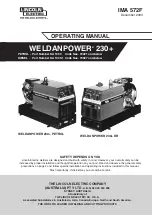


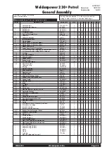

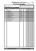

IMA 572F
Weldanpower 230+
Page 11
Location / Ventilation:
The welder should be located to provide an unrestricted flow of
clean, cool air to the cooling air inlets and to avoid heated air
coming out of the welder recirculating back to the cooling air inlet.
Also, locate the welder so that engine exhaust fumes are properly
vented to an outside area.
•
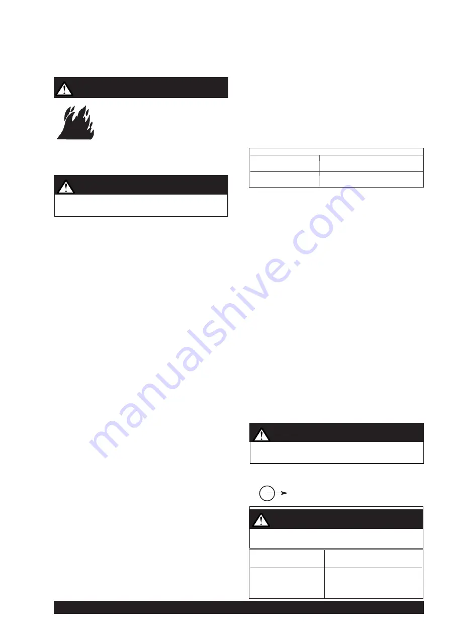
Damage to the fuel tank may cause fire
or explosion. Do not drill holes in, or
weld to the base of the Weldanpower
230+.
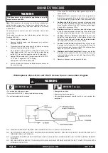
Connection of Lincoln Electric Wire Feeders:
Wire Feed (Constant Voltage)
Connection of the LN-22 and LN-25 to the Weldanpower 230+
a.
Shut the welder off
b.
Connect the electrode cable from the LN-22 or LN-25 to the
“ELECTRODE” terminal of the welder. Connect the work
cable to the “TO WORK” terminal of the welder.
c.
Position the welder “Polarity” switch to the desired polarity,
either DC (-) or DC (+).
d.
Position the “RANGE” switch to the “WIRE FEED” position
(extreme clockwise).
e.
Attach the single lead from the LN-22 or LN-25 control box
to the work using the spring clip on the end of the lead - it
carries no welding current.
f.
Place the idler switch in the “AUTO” position.
g.
Adjust wire feed speed at the LN-22 or LN-25 and adjust
the welding voltage with the output “CONTROL” at the
welder.
Note: The welding electrode is energised at all times, unless
an LN-25 with built-in contactor is used. If the output
“CONTROL” is set below “3”, the LN-25 contactor may not
pull in.
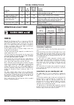
High Frequency Generator for TIG Welding Applications:
(Requires 240 - 115V, 150VA, Transformer).
K930-2 TIG Module
- Provides high frequency and shielding gas
control for AC and DC GTAW (TIG) welding applications. Its
compact case is designed for easy carrying, complete with a
handle. High frequency bypass is built in. The K938-1 Contactor
Kit must be field installed in the TIG Module when used with a
Weldanpower 230+. Additionally, the K936-3 control cable is
required if remote control is used. If remote control is not used the
K936-4 control cable is required.
The TIG Module is supplied without accessories. Arc Start
switches, amptrols, cables, torches and mounting brackets must
be purchased separately.
OPERATING INSTRUCTIONS
Additional Safety Precautions
Always operate the welder with the roof and case sides in place
as this provides maximum protection from moving parts and
assures proper cooling air flow.
Read and understand all Safety Precautions before operating this
machine. Always follow these and any other safety procedures
included on the machine, in this manual and in the Engine
Owner’s Manual.
Welder Operation
-
Maximum Open Circuit Voltage at 3300 RPM is 80 volts RMS.
-
Duty Cycle: 100% for both welding and auxiliary power.
Welder Controls -
Function and Operation
“Stop/Run” Switch & “Start” Button -
Petrol Engine only
Place the ‘Stop/Run” Switch in the “Run” position, then press the
“Start” button. The starter motor is energised to crank the engine.
Hold in the “Start” button to crank the engine; release as the
engine starts. Do not depress the “Start” button while the engine
is running as this can cause damage to the ring gear and/or
starter motor.
To stop the machine, place the “Stop/Run” switch in the “Stop”
position.
“Start” Button - Diesel Engine only
The push button start switch is pressed and held to engage the
starter motor. Once engine starts, release the button.
Notes:
-
Do not press start button while engine is running.
-
(Petrol & Diesel engines) - Do not crank the engine for
longer than 20 seconds. If the engine does not start,
allow at least 1 minute between crank periods to avoid
damage to electrical components.
“Stop” Cable - Diesel Engine only
Stop the engine by pulling the stop cable and hold it “out” until the
engine has stopped.
“Polarity” Switch
“ Range” Switch
Shut off welder before making any electrical connections.
WARNING
WARNING
Never change the “Polarity” switch setting while welding.
This will damage the switch.
CAUTION
Process
Maximum Current
on each setting
Stick/TIG - CC
50, 70, 90
6 Range Settings
125, 175, 210 DC/230 AC
Wire Feed - CV
1 Range Setting
200
Never change the “RANGE” Switch setting while welding.
This will damage the switch.
CAUTION
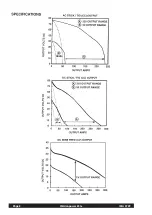
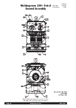
Weldanpower 230+
Constant Current
230 Amps AC @ 25 Volts
210 Amps DC @ 25 Volts
Constant Voltage
200Amps DC @ 20 Volts