background image

English 9 English 

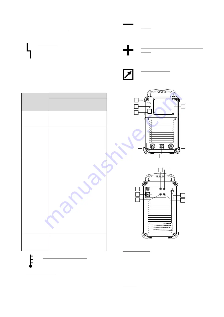
Controls and Operational Features 

1.  Power Switch ON/OFF (I/O): Controls the input power. 

Be sure the power source is properly connected to the 
mains supply before turning power on ("I"). 


2.  Status Light: A two color light that indicates 

system errors. Normal operation is steady 
green light. Error conditions are indicated, per 
Table 1. 


NOTE:

 The status light will flash green, and sometimes 

red and green, for up to one minute when the machine is 
first turned on. When the power source is powered it can 
take as long as 60 seconds for the machine to be ready to 
weld. This is a normal situation as the machine goes 
through initialization. 
 

Table 1. 

LED Light 
Condition 

Meaning 

Only machines which using 

ArcLink

®

 protocol for 

communication 

Steady Green 

System OK. Power source is 
operational, and is communicating 
normally with all healthy peripheral 
equipment. 

Blinking Green 

Occurs during power up or a system 
reset, and indicates the power source 
is mapping (identifying) 
each component in the system. 
Normal for first 1-10 seconds after 
power is turned on, or if the system 
configuration is changed during 
operation. 

Alternating Green 

and Red 

If the status lights are flashing any 
combination of red and green, errors 
are present in the power source. 
 
Individual code digits are flashed in 
red with a long pause between digits. 
If more than one code is present, the 
codes will be separated by green light. 
Read the error code before the 
machine is turned off. 
 
If occurs, to clear the error try to turn 
Off the machine, wait for a few 
seconds, then turn ON again. If the 
error remains, a maintenance is 
required. Please contact the nearest 
authorized technical service center or 
Lincoln Electric and report the error 
code read. 

Steady Red 

Indicate no communication between 
the power source and device which 
has been connected to this power 
source. 

 
3. Thermal Overload Indicator: It indicates 

that the machine is overloaded or that the 
cooling is not sufficient. 


4.  Replaceable Panel: User Interface can be installed, in 

place of the replaceable panel, which allows to adjust 
the welding parameters from the power source. Panel 
with User Interface Kit can be purchased separately 
(see "Accessories" chapter). 


5.  Negative Output Socket for the Welding 

Circuit: Depending on the configuration of 
power source, for connecting a work lead, 

the electrode holder with lead or the source/wire 
feeder welding cable. 


6.  Positive Output Socket for the Welding 

Circuit: Depending on the configuration of 
power source, for connecting a work lead, 

the electrode holder with lead or the source/wire 
feeder welding cable.. 


7.  Control Receptacle: 5 pins receptacle for 

wire feeder or remote controller 
connection. To communication wire 
feeder or remote controller with power 
source is used ArcLink

®

 protocol. 

1

3

4

5

6

7

2


Figure 1. 


8

14

9

10

13

12

11


Figure 2. 

 
8.  Power lead (5m): Connect the supply plug to the 

existing input cable that is rated for the machine as 
indicated in this manual, and conforms to all applicable 
standards. This connection shall be performed by a 
qualified person only. 

 
9.  Fuse F3: Use the 12,5A/400V (6,3x32mm) slow-blow 

fuse. See "Spare Parts" chapter. 

 
10. Fuse F4: Use the 6,3A/400V (6,3x32mm) slow-blow 

fuse. See "Spare Parts" chapter. 


Summary of Contents for SPEEDTEC 405S

Page 1: ...IM3048 08 2020 REV09 SPEEDTEC 405S 405SP 505S 505SP OPERATOR S MANUAL ENGLISH Lincoln Electric Bester Sp z o o ul Jana III Sobieskiego 19A 58 263 Bielawa Poland www lincolnelectric eu ...

Page 2: ...ie na tej stronie danych identyfikacyjnych wyrobów Nazwa modelu Kod i Numer Seryjny które możecie Państwo znaleźć na tabliczce znamionowej wyrobu Nazwa Modelu Kod i Numer Seryjny Data i miejsce zakupu ENGLISH INDEX Technical Specifications 1 ECO design information 3 Electromagnetic Compatibility EMC 5 Safety 6 Intoduction 8 Installation and Operator Instructions 8 WEEE 13 Spare Parts 13 REACh 13 A...

Page 3: ...ent Output Voltage 405S 405SP GMAW 60Vdc 80 400A 34Vdc 100 390A 33 5Vdc FCAW 60Vdc 80 400A 34Vdc 100 390A 33 5Vdc SMAW 60Vdc 80 400A 36Vdc 100 390A 35 6Vdc GTAW 60Vdc 80 400A 26Vdc 100 390A 25 6Vdc 505S 505SP GMAW 60Vdc 60 500A 39Vdc 100 390A 33 5Vdc FCAW 60Vdc 60 500A 39Vdc 100 390A 33 5Vdc SMAW 60Vdc 60 500A 40Vdc 100 390A 35 6Vdc GTAW 60Vdc 60 500A 30Vdc 100 390A 25 6Vdc WELDING CURRENT RANGE G...

Page 4: ...h 405S 405SP 50 kg 535 mm 300 mm 635 mm 505S 505SP 50 kg 535 mm 300 mm 635 mm Protection Rating Operating Humidity t 20 C 405S 405SP IP23 90 505S 505SP Operating Temperature Storage Temperature 405S 405SP from 10 ºC to 40 ºC from 25 ºC to 55 ºC 505S 505SP ...

Page 5: ...e condition specified in below table IDLE STATE Condition Presence MIG mode X TIG mode STICK mode After 30 minutes of non working Fan off X The value of efficiency and consumption in idle state have been measured by method and conditions defined in the product standard EN 60974 1 20XX Manufacturer s name product name code number product number serial number and date of production can be read from ...

Page 6: ... process gas usage depends on cross sectional area of the nozzle For comonnly used torches Helium 14 24 l min Argon 7 16 l min Notice Excessive flow rates causes turbulence in the gas stream which may aspirate atmospheric contamination into the welding pool Notice A cross wind or draft moving can disrupt the shielding gas coverage in the interest of saving of protective gas use screen to block air...

Page 7: ...ds Check the electromagnetic immunity for equipment operating in or near the work area The operator must be sure that all equipment in the area is compatible This may require additional protection measures The dimensions of the work area to consider will depend on the construction of the area and other activities that are taking place Consider the following guidelines to reduce electromagnetic emi...

Page 8: ...al electrical regulations ELECTRICALLY POWERED EQUIPMENT Regularly inspect the input electrode and work clamp cables If any insulation damage exists replace the cable immediately Do not place the electrode holder directly on the welding table or any other surface in contact with the work clamp to avoid the risk of accidental arc ignition ELECTRIC AND MAGNETIC FIELDS MAY BE DANGEROUS Electric curre...

Page 9: ...ing gas for the process used and properly operating regulators designed for the gas and pressure used Always keep cylinders in an upright position securely chained to a fixed support Do not move or transport gas cylinders with the protection cap removed Do not allow the electrode electrode holder work clamp or any other electrically live part to touch a gas cylinder Gas cylinders must be located a...

Page 10: ...jury or equipment damage Read the section on electromagnetic compatibility in this manual Do not operate in areas with an ambient temperature greater than 40 C Duty cycle and Overheating The duty cycle of a welding machine is the percentage of time in a 10 minute cycle at which the welder can operate the machine at rated welding current Example 60 duty cycle Welding for 6 minutes Break for 4 minut...

Page 11: ...ff the machine wait for a few seconds then turn ON again If the error remains a maintenance is required Please contact the nearest authorized technical service center or Lincoln Electric and report the error code read Steady Red Indicate no communication between the power source and device which has been connected to this power source 3 Thermal Overload Indicator It indicates that the machine is o...

Page 12: ...ower source Insert the positive welding cable into the output socket 6 Insert the wire feeder control cable into the socket 7 see Accessories chapter Source wire feeder cable K10349 PG xM or K10349 PGW xM Use the shortest possible cable lengths Water Cooler Connection SPEEDTEC 405S 405SP 505S and 505SP work with the water cooler COOLARC 46 see Accessories chapter WARNING Read and understand the co...

Page 13: ...tion indicator 3 will turn on The Power Source is also electronically protected against overload and accidental short circuit The overload and short circuit protection circuit automatically reduces the output current to a safe value when it detects an overload Transport Lifting WARNING Falling equipment can cause injury and damage to unit Figure 7 During transportation and lifting with a crane adh...

Page 14: ... be disconnected from the machine before each maintenance and service After each repair perform proper tests to ensure safety Customer Assistance Policy The business of The Lincoln Electric Company is manufacturing and selling high quality welding equipment consumables and cutting equipment Our challenge is to meet the needs of our customers and to exceed their expectations On occasion purchasers ...

Page 15: ... First read the Part List reading instructions above then refer to the Spare Part manual supplied with the machine that contains a picture descriptive part number cross reference REACh 11 19 Communication in accordance with Article 33 1 of Regulation EC No 1907 2006 REACh Some parts inside this product contain Bisphenol A BPA EC 201 245 8 CAS 80 05 7 Cadmium EC 231 152 8 CAS 7440 43 9 Lead EC 231 ...

Page 16: ...14072 1 LF45 Digital Wire Feeder K14083 1 LF45S Digital Wire Feeder K14106 1 PF40 Digital Wire Feeder K14107 1 PF42 Digital Wire Feeder K14108 1 PF44 Digital Wire Feeder K14109 1 PF46 Digital Wire Feeder K14110 1 PF24 Digital Wire Feeder K14121 1 Replaceable Front Panel with User Interface A K14122 1 Replaceable Front Panel with User Interface B K14123 1 Replaceable Front Panel with User Interface...

Reviews: