background image

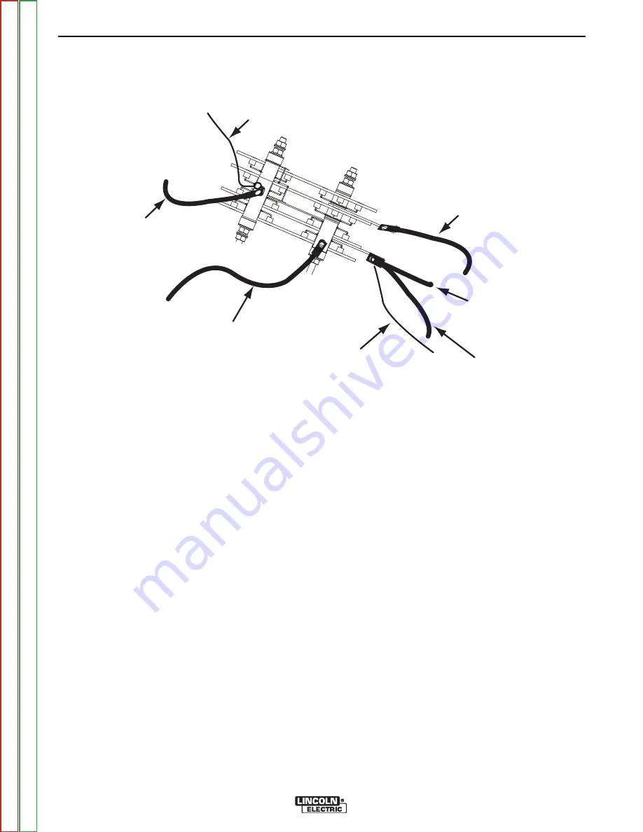
(—)

(+)

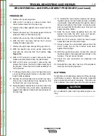
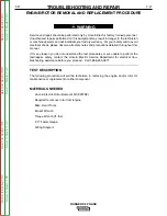
TO POLARITY SWITCH (S2)

LEAD 8

 TO CHOKE

(L1)

LEAD 254

TO STATOR (LEAD W1)

TO STATOR (LEAD S2)

TO RANGE SWITCH (S1)

AC2

AC1

FIGURE F.11 – OUTPUT RECTIFIER

OUTPUT RECTIFIER BRIDGE REMOVAL 

AND REPLACEMENT

PROCEDURE (continued)

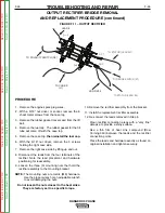
PROCEDURE

1.  Remove the engine spark plug wires.

2.  With  a  5/16”  nut  driver  or  socket,  remove  the  6

sheet metal screws from the case top.

3.  Remove the rubber gasket (cover seal) from the lift

bail.

4.  Remove the fuel cap.  The rubber gasket for the fill

tube will come off with the case top.

5.  Remove the case top,

then reinstall the fuel cap.

6.  With  the  5/16”  nut  driver,  remove  the  5  screws

holding the right case side.

7.  Remove the right case side by lifting up and out.

8. Disconnect the leads from the four terminals of the

rectifier.  Note  the  lead  placement  and  hardware
positioning for reassembly.

9. Loosen  the  three  (3)  mounting  nuts  that  hold  the

rectifier assembly to the mounting bracket.

NOTE:

The  mounting  nuts  are  metric  (M8)  hardware.
Use the proper wrench or an adjustable wrench
to avoid damaging the nuts.

Do not loosen the nuts closest to the heat sinks.

They are factory set to a specific torque.

10. Remove the rectifier assembly from the bracket.

11. Install the replacement rectifier assembly.

12. Re-connect the leads removed in Step 8.

Clean  rectifier  connection  areas  with  a  “very  fine”
abrasive to provide a shiny surface.

Use  a  thin  film  of  heat  sink  compound  (Dow
Corning  340)  between  the  leads  and  the  rectifier
connection points.

Place the leads and hardware exactly as found on
original installation and tighten securely.

TROUBLESHOOTING AND REPAIR

F-46

F-46

RANGER® 3 PHASE

Return 

to 

Section 

T

OC

Return 

to 

Section 

T

OC

Return 

to 

Section 

T

OC

Return 

to 

Section 

T

OC

Return 

to 

Master 

T

OC

Return 

to 

Master 

T

OC

Return 

to 

Master 

T

OC

Return 

to 

Master 

T

OC

Summary of Contents for RANGER 3PHASE SVM207-A

Page 1: ... TAINED THROUGHOUT And most importantly think before you act and be careful SERVICE MANUAL For use with machine code number 11079 11419 RANGER 3 Phase Sales and Service through Subsidiaries and Distributors Worldwide Cleveland Ohio 44117 1199 U S A TEL 216 481 8100 FAX 216 486 1751 WEB SITE www lincolnelectric com World s Leader in Welding and Cutting Products Copyright Lincoln Global Inc Return t...

Page 2: ...HEIR DOCTOR BEFORE OPERATING Read and understand the following safety highlights For additional safety information it is strongly recommended that you purchase a copy of Safety in Welding Cutting ANSI Standard Z49 1 from the American Welding Society P O Box 351040 Miami Florida 33135 or CSA Standard W117 2 1974 A Free copy of Arc Welding Safety booklet E205 is available from the Lincoln Electric C...

Page 3: ...en arc welding Headshield and filter lens should conform to ANSI Z87 I standards 4 b Use suitable clothing made from durable flame resistant material to protect your skin and that of your helpers from the arc rays 4 c Protect other nearby personnel with suitable non flammable screening and or warn them not to watch the arc nor expose themselves to the arc rays or to hot spatter or metal ELECTRIC S...

Page 4: ...near hydraulic lines Have a fire extinguisher readily available 6 b Where compressed gases are to be used at the job site special precautions should be used to prevent hazardous situations Refer to Safety in Welding and Cutting ANSI Standard Z49 1 and the operating information for the equipment being used 6 c When not welding make certain no part of the electrode circuit is touching the work or gr...

Page 5: ...uttes de laitier en fusion sont émises de l arc de soudage Se protéger avec des vêtements de protection libres de l huile tels que les gants en cuir chemise épaisse pan talons sans revers et chaussures montantes 5 Toujours porter des lunettes de sécurité dans la zone de soudage Utiliser des lunettes avec écrans lateraux dans les zones où l on pique le laitier 6 Eloigner les matériaux inflammables ...

Page 6: ...ufacturer In some cases this remedial action may be as simple as earthing grounding the welding circuit see Note In other cases it could involve construction of an electromagnetic screen enclosing the power source and the work com plete with associated input filters In all cases electromagnetic disturbances must be reduced to the point where they are no longer troublesome Note The welding circuit ...

Page 7: ...short as possible and should be positioned close together running at or close to floor level Equipotential Bonding Bonding of all metallic components in the welding installation and adjacent to it should be considered However metallic components bonded to the work piece will increase the risk that the operator could receive a shock by touching these metallic components and the electrode at the sam...

Page 8: ...NS I I RANGER 3 PHASE Page Safety i iv Installation Section A Operation Section B Accessories Section C Maintenance Section D Theory of Operation Section E Troubleshooting and Repair Section F Electrical Diagrams Section G Parts Manual P 496 ...

Page 9: ...ation A 5 Lifting A 5 High Altitude Operation A 5 Muffler Relocation A 5 Location Ventilation A 6 Connection of Wire Feeders A 6 Additional Safety Precautions A 6 Welder Operation A 6 Auxiliary Power A 7 Motor Starting A 8 Stand by Power Connections A 8 Auxiliary Power While Welding A 8 Connection of RANGER 3PHASE to Premises Wiring Drawing A 9 Extension Cord Recommendations A 10 Electrical Device...

Page 10: ...hler CH23S Description 2 cylinder 4 Cycle Air Cooled Gasoline Engine Aluminum Alloy with Cast Iron Liners Electronic Ignition Operating Speed RPM High Idle 3700 Full Load 3500 Low Idle 2200 Displacement cu in cu cm 38 624 Kohler CH20S 41 674 Kohler CH23S Capacities Fuel 9 Gal 34 L Lubricating Oil 2 0 Qts 1 9 L Horsepower 20 HP 3600 RPM 23 HP 3600 RPM Starting System 12VDC Battery Electric Start Gr...

Page 11: ...s be equipped with exhaust spark arresters when they are operated in certain locations where unarrested sparks may present a fire hazard The standard muffler included with this welder does not qualify as a spark arrester When required by local reg ulations the K894 1 spark arrester must be installed and properly maintained An incorrect arrester may lead to damage to the engine or adversely affect ...

Page 12: ...peed rough ness of surface on which the trailer will be operated environmental conditions 5 Conformance with federal state and local laws 1 1 Consult applicable federal state and local laws regarding specif ic requirements for use on public highways PRE OPERATION SERVICE READ the engine operating and maintenance instructions supplied with this machine CAUTION LUBRICATION SYSTEM CAPACITY INCLUDING ...

Page 13: ...des elder output de rating may be necessary For maximum rating de rate the welder output 3 5 for every 1000ft 305m above 3000ft 914m If operation will consistently be at altitudes above 5 000 ft 1525m a carburetor jet designed for high altitudes should be installed This will result in better fuel economy cleaner exhaust and longer spark plug life It will not give increased power Contact your local...

Page 14: ...R 3 PHASE Constant Current 225 Amps AC 25 Volts 210 Amps DC 25 Volts Constant Voltage 200 Amps DC 20 Volts c Position the welder Polarity switch to the desired polarity either DC or DC d Position the RANGE switch to the WIRE FEED position e Attach the single lead from the LN 25 control box to the work using the spring clip on the end of the lead it carries no welding current f Place the engine swi...

Page 15: ... front of Machine AUXILIARY POWER Do not connect any plugs that connect to the power receptacles in parallel Start the engine and set the IDLER control switch to the High Idle mode Set the CONTROL to 10 Voltage is now correct at the receptacles for auxiliary power This must be done before a tripped GFCI receptacle can be reset properly See the MAINTE NANCE section for more detailed information on ...

Page 16: ... power can be adapted to the particular installation and comply with all applicable electrical codes The following informa tion can be used as a guide by the electrician for most applications refer also to the connection diagram shown in Figure A 1 TABLE A 1 SIMULTANEOUS WELDING AND POWER Output Selector Permissible Power Permissible Auxiliary Setting Watts Unity Power Current in Amperes Factor 12...

Page 17: ...CE OVERCURRENT PROTECTION 50 AMP 120 240 VOLT PLUG NEMA TYPE 14 50 50 AMP 120 240 VOLT RECEPTACLE Connection of RANGER 3 PHASE to premises wiring must be done by a licensed electrician and must com ply with the National Electrical Code and all other applicable electrical codes See the Installation Section for important information about not using the 480V 3 Phase Receptacle for connection to Singl...

Page 18: ...ion can cause the capaci tative elements to fail Surge protection transient protection and additional loading is recom mended for 100 fail safe oper ation DO NOT RUN THESE DEVICES WITHOUT ADDI TIONAL RESISTIVE TYPE LOADS Inductive Single phase induction motors These devices require large drills well pumps grinders small current inrush for starting refrigerators weed and hedge Some synchronous moto...

Page 19: ...tions B 2 General Description B 2 Case Front Controls B 2 Fuel Consumption B 3 Welding Processes B 4 Starting Shutdown Instructions B 6 Starting the Engine B 6 Stopping the Engine B 6 Break in Period B 6 Return to Master TOC Return to Master TOC Return to Master TOC Return to Master TOC ...

Page 20: ...ower is being drawn from the receptacles and not welding for 10 14 seconds the idler reduces the engine speed to low idle SAFETY PRECAUTIONS Do not attempt to use this equipment until you have thoroughly read the engine manufacturer s manual supplied with your welder It includes important safety precautions detailed engine starting operating and maintenance instructions and parts lists ELECTRIC SH...

Page 21: ... range settings WIRE FEED constant voltage one range setting 90 Max 145 Max 210DC 225AC Max 15 to 25V 50 to 90 Amps 70 to 145 Amps 120 to 210 DC 225 AC Up to 200 Amps RANGER 3 PHASE APPROXIMATE FUEL CONSUMPTION KOHLER CH20S or CH23S 35 Gallons Hour 1 34 Liters Hour 76 Gallons Hour 2 86 Liters Hour 1 23 Gallons Hour 4 64 Liters Hour 1 38 Gallons Hour 5 21 Liters Hour 1 22 Gallons Hour 4 60 Liters H...

Page 22: ... used in the AUTO position but the delay going to flow idle after welding is ceased will be increased if the AFTER FLOW CONTROL is set above 10 seconds WIRE FEED WELDING PROCESSES CONSTANT VOLTAGE The Innershield electrode recommended for use with the RANGER 3 PHASE is NR 212 MP The electrode sizes and welding ranges that can be used with the RANGER 3 PHASE are shown in the following table The RAN...

Page 23: ...ine goes to high idle NOTE Output Control must be set above 3 TIG TIG MODULE WITH Yes High Cold Press Arc Start Switch WITH CONTACTOR KIT contactor closes CONTROL CABLE ARC welding starts immediately START SWITCH WIRE FEED LN 15 No Auto Cold Press gun trigger ACROSS the ARC LN 15 contactor closes has internal contactor Welding starts immediately NOTE Output Control must be set above 3 on the dial ...

Page 24: ...ol the engine Stop the engine by placing the Engine switch in the OFF position A fuel shut off valve is not required on the RANGER 3 PHASE because the fuel tank is mounted below the engine BREAK IN PERIOD It is normal for any engine to use a greater amount of oil until the break in is accomplished Check the oil level twice a day during the break in period approxi mately 50 running hours IMPORTANT ...

Page 25: ...E OF CONTENTS ACCESSORIES SECTION C 1 C 1 RANGER 3 PHASE Accessories C 1 Optional Equipment C 2 Recommended Equipment C 3 Return to Master TOC Return to Master TOC Return to Master TOC Return to Master TOC ...

Page 26: ...VA plug rated at 120 240V 50 amps K704 ACCESSORY KIT Includes 35 ft 10 7m 2 0 AWG electrode cable 30 ft 9 1m 2 0 AWG work cable head shield Filterplate work clamp and electrode holder 400 Amp Capacity K875 ACCESSORY KIT Includes 20 ft 6 1m 6 electrode cable headshield filter plate work clamp electrode holder and sample pack of mild steel electrodes 150 Amp Capacity lug 15ft 4 6 6 work cable K894 1...

Page 27: ...c operation no control cable Provides cold elec trode until gun trigger is pressed Includes gas sole noid Requires Drive Roll Kit and Weld Power Cable Magnum Gun and Magnum Gun Connector Kit are required for gas shielded welding Magnum Innershield Gun and wire bushing is required for gasless welding TIG PRO TORCH TIG Torch K1783 9 PTA 26V TIG Torch Magnum Parts Kit and Argon Gas KP509 Parts Kit K9...

Page 28: ...NOTES C 4 C 4 RANGER 3 PHASE Return to Section TOC Return to Section TOC Return to Section TOC Return to Section TOC Return to Master TOC Return to Master TOC Return to Master TOC Return to Master TOC ...

Page 29: ...ne Maintenance D 2 Changing the Oil D 2 Oil Capacity D 2 Oil Filter D 3 Air Cleaner General Maintenance D 3 GFCI Test Reset Procedure D 3 Slip Rings D 3 Battery D 4 Engine Maintenance Parts D 4 Major Component Location D 5 Return to Master TOC Return to Master TOC Return to Master TOC Return to Master TOC ...

Page 30: ...efer to the maintenance section of the Engine Owner s Manual for more information NOTE Engine life will be reduced if the oil and oil fil ter are not changed according to the manufac turer s recommendation ENGINE OIL CHANGE Drain the oil while the engine is warm to assure rapid and complete draining Remove the oil filler cap and dipstick Remove the yellow cap from the oil drain valve and attach th...

Page 31: ...odically In particularly dirty locations this may be required once a week Output Ranger Selector and Polarity Switches Switch contacts should not be greased To keep contacts clean rotate the switch through its entire range frequently Good practice is to turn the handle from maximum to minimum setting twice each morning before starting to weld GFCI RECEPTACLE TESTING AND RESET TING PROCEDURE The GF...

Page 32: ...EW BATTERY disconnect negative cable from old battery first and connect to new battery last CONNECTING A BATTERY CHARGER Remove bat tery from welder by disconnecting negative cable first then positive cable and battery clamp When rein stalling connect negative cable last Keep well venti lated USING A BOOSTER connect positive lead to battery first then connect negative lead to engine foot BATTERY A...

Page 33: ...UT RECTIFIER ASSEMBLY 3 BASE UNDERCARRIAGE ASSEMBLY 4 ENGINE ROTOR STATOR ASSEMBLY 5 CASE TOP SIDES 2 2 1 1 3 3 4 4 5 5 Return to Section TOC Return to Section TOC Return to Section TOC Return to Section TOC Return to Master TOC Return to Master TOC Return to Master TOC Return to Master TOC ...

Page 34: ...NOTES D 6 D 6 RANGER 3 PHASE Return to Section TOC Return to Section TOC Return to Section TOC Return to Section TOC Return to Master TOC Return to Master TOC Return to Master TOC Return to Master TOC ...

Page 35: ...GE REGULATOR BATTERY HOUR METER OIL PRESSURE SWITCH STARTER FUEL SHUTOFF SOLENOID STARTER SOLENOID ENGINE CONTROL SWITCH 4 3 2 1 Z Y 3 5 6 X 120 230 VOLT BREAKERS AND RECEPTACLES EXCITER WINDING AUXILIARY WINDINGS WELD WINDINGS Z X Y 480 VOLT 3 PHASE BREAKER AND RECEPTACLE W2 C1 W1 TOROID TOROID 254 3 6 X Lead 254 1 turn through the toroid Leads 3 6 two turns through the toroid in opposite directi...

Page 36: ...and the engine will drop to low speed Upon striking an arc or drawing of current from any of the Auxiliary Power receptcles the solenoid will release and the engine will go to the high idle speed Once the load is removed and after a 10 second delay it will return to the low idle condition The Hour Meter runs whenever the oil pressure switch is closed to help keep track of running time for mainte n...

Page 37: ...k to the rotor slip rings This regulated supply is used to control the voltage output of the welder A diode on the PC Board is used to isolate the exciter voltage from the engine 12 VDC supply The Output Control is used to adjust the weld voltage The Idler Circuit is also controlled by the Control PC Board A Toroid is used to sense current draw through either the weld circuit or any of the auxilia...

Page 38: ... is fed to the Output Rectifier to be converted to DC The positve output of the rectifier is then routed through the Choke to smooth out the ripple and provide good weld ing characteristics Lead 254 is a sense lead that is connected in parallel to the lead from the Range Switch to the AC side of the rectifier and as a result shares a portion of the weld cur rent It is routed through the toroid to ...

Page 39: ...Mode F 30 Typical DC Weld Output Waveform CC Mode F 31 Typical AC Weld Output Waveform F 32 Abnormal Open Circuit Weld Voltage Waveform CV Mode F 33 Abnormal Open Circuit DC Weld Voltage Waveform F 34 Normal Open Circuit Weld Voltage Waveform CV Mode F 35 Normal Open Circuit DC Weld Voltage Waveform CC Mode F 36 Normal Open Circuit AC Weld Voltage Waveform F 37 Removal and Replacement Procedures F...

Page 40: ...mponents in the order listed to eliminate one possibility at a time until you locate the cause of your problem All of the referenced test procedures referred to in the Troubleshooting Guide are described in detail at the end of this chapter Refer to the Troubleshooting and Repair Table of Contents to locate each specific Test Procedure All of the specified test points components terminal strips et...

Page 41: ...paper plastic or cloth which could have a static charge If the PC board can t be installed immediately put it back in the static shield ing bag If the PC board uses protective shorting jumpers don t remove them until installation is complete If you return a PC board to The Lincoln Electric Company for credit it must be in the static shielding bag This will prevent further damage and allow prop er ...

Page 42: ...to the rotor slip rings 1 Check for the presence of 12 VDC at the pc board from lead 224 to frame ground This is the supply voltage to the board and is present when the engine is running and the S3 switch is in the HIGH or AUTO posi tion If the 12VDC is missing check the leads switches and connections associated with the lead 224 See the Wiring Diagram 2 Perform the Rotor Voltage Test 3 If Rotor V...

Page 43: ...ounded to the stator iron Replace the Sstator if necessary If the cor rect AC voltage is present pro ceed to step 2 2 Check the Reactor Range Switch S1 and associated wires for loose or faulty connec tions Check the reactor wind ing for continuity and test to be sure it is NOT grounded to the reactor iron 3 Check the Choke L1 Polarity Switch S2 and associated wires for loose or faulty connec tions...

Page 44: ...he operation of the Polarity Switch S2 Also check the associated wires for loose or faulty connections See Wiring Diagram 2 Check for continuity from lead S2 to lead E located in the main stator See Wiring Dia gram No constant voltage CV welding output Constant current CC and the auxiliary power are operating normally 1 Make sure the Range Switch S1 is in the proper position CV and seated correctl...

Page 45: ...1 Check that the leads are cor rectly wrapped through the Toroid See Wiring Diagram 2 Perform the Toroid Test 3 The Printed Circuit Board may be faulty Replace TROUBLESHOOTING AND REPAIR F 7 F 7 RANGER 3 PHASE Engine will not go to high idle when attempting to weld Welding output is normal when Idler Switch is in HIGH position Automatic idle function works properly when the auxiliary power is load...

Page 46: ... prevent ing it from functioning 2 If there is NOT 12VDC at leads 213 to 215 then test for 12VDC from lead 213 to ground lead 5 See Wiring Diagram If 12VDC is present then check lead 215 for conti nuity zero ohms from the Idler Solenoid to the Printed Circuit Board plug 3J1 If lead 215 is OK then the Printed Circuit Board may be faulty Replace 3 If there is NOT 12VDC from lead 213 to ground lead 5...

Page 47: ...n shuts off when switched to run 1 Oil pressure switch may be faulty 2 Fuel Shutoff Solenoid Diodes may be open 1 Check Oil Switch should show continuity when running open when off Switch Replace oil pressure switch if necessary 2 Check engine diodes in engine wiring harness Replace if necessary Engine Mfg Part Engine will not start with S3 in start position but then tries to start or does start w...

Page 48: ...agram 2 If the OCV is low at the welder output terminals perform The Engine Throttle Adjustment Test 3 Perform the Output Rectifier Bridge Test 4 Check for shorted or grounded windings in the reactor and also in the main stator See Wiring Diagram TROUBLESHOOTING AND REPAIR F 10 F 10 RANGER 3 PHASE Welding output is low with little or no control Auxiliary output is also low 1 Check the brushes for ...

Page 49: ...act the Lincoln Electric Service Department for electrical trou bleshooting assistance before you proceed Call 1 888 935 3877 TEST DESCRIPTION This test will determine if the correct DC voltage is being applied to the rotor at maximum engine speed 3700 RPM This information will aid the technician in determining if the generator field is operating properly MATERIALS NEEDED Volt Ohmmeter Misc Hand T...

Page 50: ...ation 9 Connect the negative meter probe to the other brush lead 219 10 Start the engine and run it at high idle Set the out put control to the MAXIMUM position position 10 11 Check the voltage reading on the voltmeter It should read between 32 and 45 VDC 12 If the voltage reading is low or not present the generator field is not functioning properly Perform the Rotor Resistance Test 13 If the volt...

Page 51: ...rocedures or are unable to perform the test repairs safely contact the Lincoln Electric Service Department for electrical trou bleshooting assistance before you proceed Call 1 888 935 3877 TEST DESCRIPTION This test will determine if there is a shorted winding in the rotor or if the rotor is grounded MATERIALS NEEDED Volt Ohmmeter Misc Hand Tools Wiring Diagram ROTOR RESISTANCE TEST TROUBLESHOOTIN...

Page 52: ... on the low scale X1 B Check the resistance across the slip rings It should read approximately 5 ohms 13 Measure the resistance to ground A Set the ohmmeter on the high scale X100 000 B Place one probe on either of the slip rings Place the other probe on any good unpainted ground The machine ground stud works well C Check the resistance It should read very high at least 0 5 megohm 500 000 ohms If ...

Page 53: ...res or are unable to perform the test repairs safely contact the Lincoln Electric Service Department for electrical trou bleshooting assistance before you proceed Call 1 888 935 3877 TEST DESCRIPTION This test will determine if the correct AC voltages are being generated from the stator windings MATERIALS NEEDED Volt Ohmmeter Misc Hand Tools Wiring Diagram AUXILIARY AND FIELD WINDING TEST TROUBLES...

Page 54: ...the engine OFF To test the 240 VAC winding 1 With the Voltmeter set to read AC Volts use proper scale place the probes in the 240VAC receptacle where shown in Figure F 3 2 With the Output Control set at 10 Start the engine and let it run in the HIGH idle mode 3 The voltmeter should read 240 to 264 volts from lead 3 to lead 6 4 Turn the engine OFF To test the 480 VAC 3 Phase winding 1 With the Outp...

Page 55: ...he stator If the voltage readings are within specifications then the windings are good and functioning properly 6 Reinstall the case side case top fuel cap and lift bail gasket TROUBLESHOOTING AND REPAIR F 17 F 17 RANGER 3 PHASE B A D C CONTROL L12198 1 X4 DZ5 D1 C24 C39 R4 D2 X3 C31 R33 R76 R95 R82 R39 Q3 R47 C12 R72 R67 C37 R88 R45 J2 R48 D3 C30 C32 DZ8 D11 D10 C2 R5 TP2 D21 R73 D9 DZ2 DZ10 R11 ...

Page 56: ...NOTES F 18 F 18 RANGER 3 PHASE Return to Section TOC Return to Section TOC Return to Section TOC Return to Section TOC Return to Master TOC Return to Master TOC Return to Master TOC Return to Master TOC ...

Page 57: ...s or are unable to perform the test repairs safely contact the Lincoln Electric Service Department for electrical trou bleshooting assistance before you proceed Call 1 888 935 3877 TEST DESCRIPTION This test will determine if there are faulty diodes in the Output Rectifier Bridge MATERIALS NEEDED Volt Ohmmeter Analog Meter Preferred Misc Hand Tools Wiring Diagram OUTPUT RECTIFIER BRIDGE TEST TROUB...

Page 58: ...d the machine case front 10 Put the Polarity Switch in the AC Mode 11 Unplug the 12 pin connector J1 from the Control Board 12 Use an Ohmter analog meter preferred to test the Output Rectifier per the following chart NOTE Meter readings may vary depending on the type of meter Typically all LOW readings and all HIGH readings should be similar If any of the readings are not correct disconnect the le...

Page 59: ...edures or are unable to perform the test repairs safely contact the Lincoln Electric Service Department for electrical trou bleshooting assistance before you proceed Call 1 888 935 3877 TEST DESCRIPTION This procedure will aid the technician in determining whether the current sensing toroid is functioning properly MATERIALS NEEDED Volt Ohmmeter Misc Hand Tools Wiring Diagram TOROID TEST TROUBLESHO...

Page 60: ...sket for the fill tube will come off with the case top 4 Remove the case top then replace the fuel cap 5 Remove the screws holding the right case side 6 Remove the right case side by lifting up and out 7 Start the engine and set it to AUTO and wait for it to drop to low idle 2400 rpm 8 Plug a trouble light with a 100 watt bulb into one of the 120VAC receptacles The machine should go to High Idle I...

Page 61: ...s or are unable to perform the test repairs safely contact the Lincoln Electric Service Department for electrical trou bleshooting assistance before you proceed Call 1 888 935 3877 TEST DESCRIPTION This test will determine if the Flywheel Alternator Regulator and associated circuitry are functioning properly MATERIALS NEEDED Volt Ohmmeter Misc Hand Tools Wiring Diagram CHARGING CIRCUIT TEST TROUBL...

Page 62: ...f the voltage regulator to determine the charg ing voltage for the battery Run the engine at high idle 3650 RPM Set the voltmeter for DC volts and place the Positive meter probe on the middle lead and the Negative probe on the green ground wire connected to the voltage regulator See Figure F 5 The meter should read 13 15 VDC 5 If the DC voltage reading is incorrect or not pre sent the voltage regu...

Page 63: ...artment for electrical trou bleshooting assistance before you proceed Call 1 888 935 3877 TEST DESCRIPTION If the machine output is low this test will determine whether the gasoline engine is oper ating at the correct speed RPM during both HIGH and LOW idle conditions Directions for adjusting the throttle to the correct RPM are given MATERIALS NEEDED Misc Hand Tools Strobe tach frequency counter o...

Page 64: ...and synchronize it to the rotating mark 10 With the machine at HIGH IDLE the tach should read between 3700 and 3750 RPM With the machine at LOW IDLE the tach should read between 2150 and 2400 RPM 11 If either of the readings is incorrect adjust the throttle as follows Adjust HIGH IDLE Use the 3 8 wrench to turn the spring loaded adjustment nut See Figure F 8 for location of the adjustment nut Turn...

Page 65: ...nut See Figure F 7 for location of the adjustment nut Turn the nut clock wise to increase HIGH IDLE speed Adjust the speed until the frequency reads between 60 8 and 62 5 Hz Adjust LOW IDLE First make sure there is no load on the machine Set the IDLER switch to AUTO and wait for the engine to change to low idle speed Use the 3 8 wrench to adjust the solenoid nut which changes the amount of throw i...

Page 66: ...moved the top of the air cleaner is the best location 2 Start the engine and observe the whip handle of the vibratach At HIGH IDLE 3700 RPM the whip handle should exhibit maximum oscillation At LOW IDLE 2400 RPM the whip handle should exhibit minimum oscillation Note that these are median measurements vibrat ach readings may vary slightly above or below 3 If either of the vibratach indications is ...

Page 67: ...e that each vertical divi sion represents 50 volts and that each horizontal division represents 5 mil liseconds in time Note Scope probes connected at machine 115 VAC receptacle NORMAL OPEN CIRCUIT VOLTAGE WAVEFORM 115 VAC SUPPLY HIGH IDLE NO LOAD OUTPUT CONTROL AT MAXIMUM 16 2 ms Return to Section TOC Return to Section TOC Return to Section TOC Return to Section TOC Return to Master TOC Return to...

Page 68: ...as loaded with a resistance grid bank Note Scope probes connected at machine 115VAC receptacle SCOPE SETTINGS Volts Div 20V Div Horizontal Sweep 5 ms Div Coupling DC Trigger Internal TYPICAL DC WELD OUTPUT WAVEFORM CV MODE MACHINE LOADED CH1 0 volts 5 ms 20 volts MACHINE LOADED TO 200 AMPS AT 20 VDC Return to Section TOC Return to Section TOC Return to Section TOC Return to Section TOC Return to M...

Page 69: ...as loaded with a resistance grid bank Note Scope probes connected at machine 115VAC receptacle SCOPE SETTINGS Volts Div 20V Div Horizontal Sweep 5 ms Div Coupling DC Trigger Internal TYPICAL DC WELD OUTPUT WAVEFORM CC MODE MACHINE LOADED MACHINE LOADED TO 200 AMPS AT 26 VDC CH1 0 volts 5 ms 20 volts Return to Section TOC Return to Section TOC Return to Section TOC Return to Section TOC Return to M...

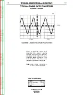
Page 70: ...ne was loaded with a resistance grid bank Note Scope probes connected at machine 115VAC receptacle SCOPE SETTINGS Volts Div 20V Div Horizontal Sweep 5 ms Div Coupling DC Trigger Internal TYPICAL AC WELD OUTPUT WAVEFORM MACHINE LOADED MACHINE LOADED TO 225 AMPS AT 25 VDC CH1 0 volts 5 ms 20 volts Return to Section TOC Return to Section TOC Return to Section TOC Return to Section TOC Return to Maste...

Page 71: ...al division represents 5 mil liseconds in time Note Scope probes connected at machine 115VAC receptacle SCOPE SETTINGS Volts Div 20V Div Horizontal Sweep 5 ms Div Coupling DC Trigger Internal ABNORMAL OPEN CIRCUIT WELD VOLTAGE WAVEFORM CV MODE HIGH IDLE NO LOAD OUTPUT CONTROL AT MAXIMUM ONE OUTPUT DIODE NOT FUNCTIONING CH1 0 volts 5 ms 20 volts Return to Section TOC Return to Section TOC Return to...

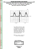
Page 72: ...tal division repre sents 5 milliseconds in time Note Scope probes connected at machine 115VAC receptacle SCOPE SETTINGS Volts Div 50V Div Horizontal Sweep 5 ms Div Coupling DC Trigger Internal ABNORMAL OPEN CIRCUIT DC WELD VOLTAGE WAVEFORM HIGH IDLE NO LOAD OUTPUT CONTROL AT MAXIMUM ONE OUTPUT DIODE NOT FUNCTIONING CH1 0 volts 5 ms 50 volts Return to Section TOC Return to Section TOC Return to Sec...

Page 73: ...econds in time Note Scope probes connected at machine 115VAC receptacle SCOPE SETTINGS Volts Div 20V Div Horizontal Sweep 5 ms Div Coupling DC Trigger Internal NORMAL OPEN CIRCUIT WELD VOLTAGE WAVEFORM CV MODE HIGH IDLE NO LOAD OUTPUT CONTROL AT MAXIMUM CH1 5 ms 20 volts Return to Section TOC Return to Section TOC Return to Section TOC Return to Section TOC Return to Master TOC Return to Master TO...

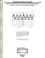
Page 74: ...conds in time Note Scope probes connected at machine 115VAC receptacle SCOPE SETTINGS Volts Div 50V Div Horizontal Sweep 5 ms Div Coupling DC Trigger Internal NORMAL OPEN CIRCUIT DC WELD VOLTAGE WAVEFORM CC MODE HIGH IDLE NO LOAD OUTPUT CONTROL AT MAXIMUM CH1 5 ms 50 volts Return to Section TOC Return to Section TOC Return to Section TOC Return to Section TOC Return to Master TOC Return to Master ...

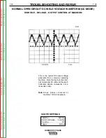
Page 75: ...iseconds in time Note Scope probes connected at machine 115VAC receptacle SCOPE SETTINGS Volts Div 50V Div Horizontal Sweep 5 ms Div Coupling DC Trigger Internal NORMAL OPEN CIRCUIT AC WELD VOLTAGE WAVEFORM HIGH IDLE NO LOAD OUTPUT CONTROL AT MAXIMUM CH1 0 volts 5 ms 50 volts Return to Section TOC Return to Section TOC Return to Section TOC Return to Section TOC Return to Master TOC Return to Mast...

Page 76: ...NOTES F 38 F 38 RANGER 3 PHASE Return to Section TOC Return to Section TOC Return to Section TOC Return to Section TOC Return to Master TOC Return to Master TOC Return to Master TOC Return to Master TOC ...

Page 77: ...edures or are unable to perform the test repairs safely contact the Lincoln Electric Service Department for electrical trou bleshooting assistance before you proceed Call 1 888 935 3877 TEST DESCRIPTION The following procedure will aid the technician in accessing the generator brushes for maintenance or replacement MATERIALS NEEDED Misc Hand Tools BRUSH REMOVAL AND REPLACEMENT PROCEDURE TROUBLESHO...

Page 78: ...at properly on the slip rings 14 To reinstall the brush holder depress the spring loaded brushes into the holder and slip a suitable non metallic fairly stiff retainer through the slots at the top and bottom of the holder A cable tie works well and will hold the brushes up so that you can easily install the holder 15 Slide the brush holder assembly back into the bracket and with the 5 16 open end ...

Page 79: ... BRUSH REMOVAL AND REPLACEMENT PROCEDURE continued TROUBLESHOOTING AND REPAIR F 41 F 41 RANGER 3 PHASE Return to Section TOC Return to Section TOC Return to Section TOC Return to Section TOC Return to Master TOC Return to Master TOC Return to Master TOC Return to Master TOC ...

Page 80: ...NOTES F 42 F 42 RANGER 3 PHASE Return to Section TOC Return to Section TOC Return to Section TOC Return to Section TOC Return to Master TOC Return to Master TOC Return to Master TOC Return to Master TOC ...

Page 81: ...ble to perform the test repairs safely contact the Lincoln Electric Service Department for electrical trou bleshooting assistance before you proceed Call 1 888 935 3877 TEST DESCRIPTION The following procedure will aid the technician in removing the printed circuit board for maintenance or replacement MATERIALS NEEDED Misc Hand Tools Wiring Diagram PRINTED CIRCUIT BOARD REMOVAL AND REPLACEMENT PRO...

Page 82: ...driver remove four self tapping screws holding the printed circuit board to the panel Be sure to follow the recommended static free meth ods for handling printed circuit boards Failure to do so can result in permanent damage to the equipment 11 Replace the old printed circuit board with a new one 12 Replace 4 self tapping screws previously removed 13 Connect the two Molex plugs and the 7 and 9 lea...

Page 83: ...form the test repairs safely contact the Lincoln Electric Service Department for electrical trou bleshooting assistance before you proceed Call 1 888 935 3877 TEST DESCRIPTION The following procedure will aid the technician in removing the output rectifier bridge for maintenance or replacement MATERIALS NEEDED Misc Hand Tools Dow Corning 340 Wiring Diagram OUTPUT RECTIFIER BRIDGE REMOVAL AND REPLA...

Page 84: ...tioning for reassembly 9 Loosen the three 3 mounting nuts that hold the rectifier assembly to the mounting bracket NOTE The mounting nuts are metric M8 hardware Use the proper wrench or an adjustable wrench to avoid damaging the nuts Do not loosen the nuts closest to the heat sinks They are factory set to a specific torque 10 Remove the rectifier assembly from the bracket 11 Install the replacemen...

Page 85: ...rvice Department for electrical trou bleshooting assistance before you proceed Call 1 888 935 3877 TEST DESCRIPTION The following procedure will aid the technician in removing the engine and or rotor for maintenance or replacement of either component MATERIALS NEEDED Lincoln Electric Rotor Removal Kit S20788 Required to remove rotor from Engine Misc Hand Tools Impact Wrench Torque Wrench ft lbs 01...

Page 86: ...ASE 1A Tolerance Ring 1B Rotor Thru Bolt 1C Blower Fan 2 Kohler Engine 3 Rotor 4 Rotor Shaft Bearing 5A Brush Bracket 5B Brush Holder 6 Engine Stator Mtg Bolts 7 Lift Bale Stator 8 Idler Plunger 9 Pull Wire 10A Idle Spring 10B Idle Washer 10C Adjustment Nut Return to Section TOC Return to Section TOC Return to Section TOC Return to Section TOC Return to Master TOC Return to Master TOC Return to Ma...

Page 87: ...ssembly The other end can remain connected 17 Disconnect the idle linkage by unsnapping the plastic clip at the engine end of the idler rod Snap the clip back onto the rod to avoid losing it remove the rod for reassembly 18 Disconnect the fuel line from the fuel tank Plug the hose and also plug the connection at the fuel tank to prevent the escape of gasoline fumes 19 Cut the cable ties and remove...

Page 88: ... The slot head must face out Screw in the bolt with the slot head screw driver until the bolt bottoms out on the engine crankshaft about 3 4 4 Turning it counterclockwise screw in the left hand thread rotor removal tool from the kit into the rotor shaft Support the rotor with one hand and tighten the tool to approximately 50 ft lbs with the torque or impact wrench 5 If the rotor does not pop off t...

Page 89: ...n the ground lead to the right engine mount ing bolt and install both bolts 7 Install the brush holder bracket back into the sta tor frame See the Brush Removal and Replacement Procedure in this section of the manual 8 Attach leads to the oil pressure switch refer to wiring diagram Replace any cut cable ties 9 Unplug the fuel tank connection and fuel hose and connect them 10 Connect the idle linka...

Page 90: ...oad Amps Volts Maximum Maximum 73 80 25 32 225 275 WELDER CV OUTPUT1 Output Control Range Switch Open Circuit Load Volts Load Amps Volts Maximum Wire Feed CV 29 33 19 23 200 220 AUXILIARY POWER RECEPTACLE OUTPUT1 230 Volt Receptacle 115 Volt Receptacle2 Open Circuit Load Volts Load Amps Open Circuit Load Volts Load Amps Voltage Voltage 246 264 216 250 34 41 5 123 132 115 130 17 5 21 FIELD AMPS AND...

Page 91: ...Machine L12259 G 3 Schematic Control PC Board L12197 1 G 4 NOTE Many PC Board Assemblies are now totally encapsulated surface mounted and or multi lay ered and are therefore considered to be unserviceable Assembly drawings of these boards are no longer provided Return to Master TOC Return to Master TOC Return to Master TOC Return to Master TOC ...

Page 92: ...1 50A 50A CB2 CB3 20A 20A CB4 3 SILVER COLORED WHITE WIRES RANGER 3 PHASE C CCW ALL CASE FRONT COMPONENTS SHOWN VIEWED FROM N A GROUNDING THIS TERMINAL STOPS THE ENGINE 210 CB7 25A R RED OR PINK B BLACK OR GRAY V VIOLET U BLUE W WHITE LEAD COLOR CODE 254 3 1 2 3 4 261 260 LEADS 254 PASSES THRU TOROID 1 TIME 211 213 208C 6A 6 LEADS 3 AND 6 2 TURNS THRU TOROID IN OPPOSITE DIRECTIONS 6 6 7 9 J2 S2 E ...

Page 93: ...2 J51 3 J51 4 Resistance of fuel solenoid cannot be accurately measured through diodes J51 Engine Connector If engine oil pressure drops below safe operating pressure the oil pressure switch opens removing 12 volts from circuit 224 shutting off fuel solenoid to stop engine Hourmeter will also stop running and PCB1 will denergize idle solenoid 224C Fuel solenoid is mounted on engine carburetor Engi...

Page 94: ... 4 NOTE This diagram is for reference only It may not be accurate for all machines covered by this manual Return to Section TOC Return to Section TOC Return to Section TOC Return to Section TOC Return to Master TOC Return to Master TOC Return to Master TOC Return to Master TOC ...

Reviews: