Lincoln Electric Magnum PRO 250 LX Operator'S Manual Download Page 17

11

TROUBLESHOOTING

MAGNUM PRO 250 LX & LX GT SPOOL GUN

Observe all Safety Guidelines detailed throughout this manual

If for any reason you do not understand the test procedures or are unable to perform the tests/repairs safely, contact your 
Lincoln Authorized Service Facility for technical troubleshooting assistance before you proceed.

WWW.LINCOLNELECTRIC.COM/LOCATOR
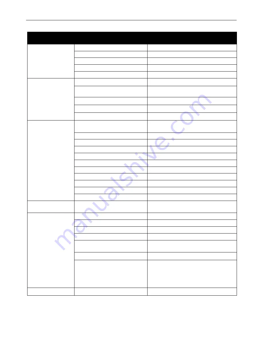
PROBLEM

(SYMPTOMS)

POSSIBLE AREAS OF 

MISADJUSTMENT(S)

RECOMMENDED COURSE OF ACTION

No arc, wire feed, or gas

flow.

1. Cable connections loose. 

1. Check all power connections.

2. Trigger switch loose or defective.

2. Fix switch or replace. 

3. Welder not turned on. 

3. Turn on welder power. 

4. Welder not plugged in. 

4. Plug in.

5. Cable or adapter cable damaged.

5. Inspect and replace

No arc, weak arc.

1. Poor ground connection to work. 

1. Check ground connection. 

2. Power cable connection loose.

2. Check connections; if defective, replace cable or

connectors. 

3. Voltage set too low.

3. Adjust to proper voltage

4. Tip too large for wire size.

4. Change tip size.

5. Wire feed speed too slow.

5. Increase wire feed speed.

No wire feed.

1. Feeding small diameter wire with large

groove on drive roller. 

1. Change position of wire drive roller.

2. Wire drive release open. 

2. Close wire drive release. 

3. Wire welded to tip. 

3. Peel wire off tip or use new tip. 

4. Wire spool empty. 

4. Insert new spool.

5. Tip too small for wire. 

5. Insert correct tip.

6. Kink or bend in wire.

6. Pull wire through tip or start new wire end.

7. Spool cover binding. 

7. Rotate spool cover slot to proper position.

8. Control cable loose. 

8. Check all connections.

9. Drive roller worn. 

9. Replace. 

10. Pressure roller stuck. 

10. Replace or lubricate. 

11. Roller spring loose or broken.

11. Replace.

Wire feed too fast or too

slow.

1. Wrong wire speed set for work.

1. Adjust wire feed speed.

Low or no gas flow.

Oxidation of work.

1. Gas flow not set right. 

1. Set proper flow rate.

2. Cylinder out of gas. 

2. Get new cylinder of gas.

3. Cylinder valve closed. 

3. Open cylinder valve. 

4. Leak in gas line. 

4. Inspect and replace. 

5. Leak in gun.

5. Check for missing gun tubes and/or missing gun

body cover.

6.Gas diffuser clogged

6. Blow out gas diffuser openings.

7. Clogged internal valve (only for K3569-2) 

7.  Remove neck and check if gas is flowing from

mechanical valve by pressing the trigger. If no gas
flow is detected, adjust first the trigger set screw
as shown in the manual page 13- replace
mechanical valve if no gas is detected.

Oxidized work, arc unstable. 1. Wrong welding polarity.

1. Check polarity.

Summary of Contents for Magnum PRO 250 LX

Page 1: ...gister Authorized Service and Distributor Locator www lincolnelectric com locator IM10484 Issue Date Nov 16 18 Lincoln Global Inc All Rights Reserved K Number K3569 2 Magnum PRO 250 LX GT K3570 2 Magn...

Page 2: ...A LARGE ROOM OR OUTDOORS natural ventilation may be adequate if you keep your head out of the fumes See below USE NATURAL DRAFTS or fans to keep the fumes away from your face If you develop unusual s...

Page 3: ...hot engine parts and igniting Do not spill fuel when filling tank If fuel is spilled wipe it up and do not start engine until fumes have been eliminated 1 d Keep all equipment safety guards covers and...

Page 4: ...m to ANSI Z87 I standards 4 b Use suitable clothing made from durable flame resistant material to protect your skin and that of your helpers from the arc rays 4 c Protect other nearby personnel with s...

Page 5: ...nt passing through lifting chains crane cables or other alternate circuits This can create fire hazards or overheat lifting chains or cables until they fail 6 h Also see item 1 c 6 I Read and follow N...

Page 6: ...CTION 6 MAKING A WELD 7 MACHINE OPERATION SECTION 7 PROCEDURE SETTINGS 8 SETTING GAS FLOW RATE 9 OPTIONAL KITS AND ACCESSORIES 10 MAINTENANCE 10 ROUTINE MAINTENANCE 10 TROUBLESHOOTING 11 HOW TO USE TR...

Page 7: ...aded to withstand the harsh conditions of being used in rugged environments NOTE Please turn off gas when not in use SPECIFICATIONS SUPPLIED wITH KP2745 364AT 3 64 Contact Tip KP2747 1A Aluminum Diffu...

Page 8: ...l of the parts listed KP2745 364AT Contact Tip 3 64 1 2mm Included KP2747 1A Aluminum Gas Diffuser Installed KP2743 1 62RA Aluminum Gas Nozzle Installed 1 8 Recess 625 ID KP2518 2 U Groove Drive Roll...

Page 9: ...l be in the 3 64 operating position Reverse roller for 030 or 035 inch 0 9 mm diameter wire 5 Gas nozzle directs gas flow around arc Pull off gas nozzle to see contact tip and gas diffuser Spool gun i...

Page 10: ...e available and the best choice depends on the type of base metals and the desired characteristics of the weldment such as ductility and strength corrosion resistance sustained service temperature and...

Page 11: ...between drive roll pressure idler roll 8 Push wire until wire end extends approximately 6 150 mm past end of gas diffuser Re engage idle roll pressure by pushing release lever down as shown above the...

Page 12: ...rive Roll Orientation B Changing Drive Roll Orientation Note The drive roll and motor shaft are left hand thread 1 Flip lid open then move release lever to the up position 2 Take wrench 10mm and loose...

Page 13: ...just gas flow per Setting Gas Flow Rate 7 Re engage wire drive by pushing release lever to down position to feed wire 8 Momentarily squeeze trigger and verify that wire feeds properly Trim wire to app...

Page 14: ...8 9 Wire Size Metal Thickness Arc Volts Wire Speed Amps DC in mm ga in mm ipm mpm 030 0 8 22 030 0 8 13 14 1 200 5 1 40 20 036 1 0 13 14 1 240 6 1 40 18 048 1 2 14 15 1 290 7 4 50 16 060 1 6 15 16 1 3...

Page 15: ...25 Thread on 550A Nozzle Tip Recessed Order KP2743 1 62RA Insulator For 550 Amp front end expendables Order KP2773 1 Contact Tips Both standard duty and heavy duty contact tips are available in a vari...

Page 16: ...1 LOCATE PROBLEM SYMPTOM Look under the column labeled PROBLEM SYMPTOMS This column describes possible symptoms that the machine may exhibit Find the listing that best describes the symptom that the...

Page 17: ...ler 1 Change position of wire drive roller 2 Wire drive release open 2 Close wire drive release 3 Wire welded to tip 3 Peel wire off tip or use new tip 4 Wire spool empty 4 Insert new spool 5 Tip too...

Page 18: ...should vary from 5K 0 ohms TESTINg THE TRIggER SwITCH Using the torch Control Cable Connector check for continuity across pins E and F when the trigger is pressed 12 Observe all Safety Guidelines det...

Page 19: ...ed 12 Test weld before adding blue loctite into the set screw hole at the trigger top red part FIGURE F 1 MECHANICAL vALvE REPLACEMENT 1 Remove the following items a Gun tube barrel b Plastic screw co...

Page 20: ...This page intentionally left blank...

Page 21: ...This page intentionally left blank...

Page 22: ...parts or electrode with skin or wet clothing l Insulate yourself from work and ground l No toque las partes o los electrodos bajo carga con la piel o ropa moja da l Aislese del trabajo y de la tierra...

Page 23: ...d Entl ftung des Arbeitsplatzes l Mantenha seu rosto da fuma a l Use ventila o e exhaust o para remover fumo da zona respirat ria l Turn power off before servicing l Desconectar el cable de ali mentac...

Page 24: ...tomer s particular purpose with respect to such information or advice As a matter of practical consideration we also cannot assume any responsibility for updating or correcting any such information or...

Reviews: