A-23
INSTALLATION
FUME EXTRACTION ARMS
MoUntinG tHe eXtension arM
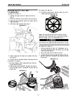
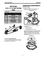
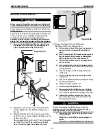
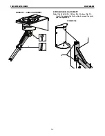
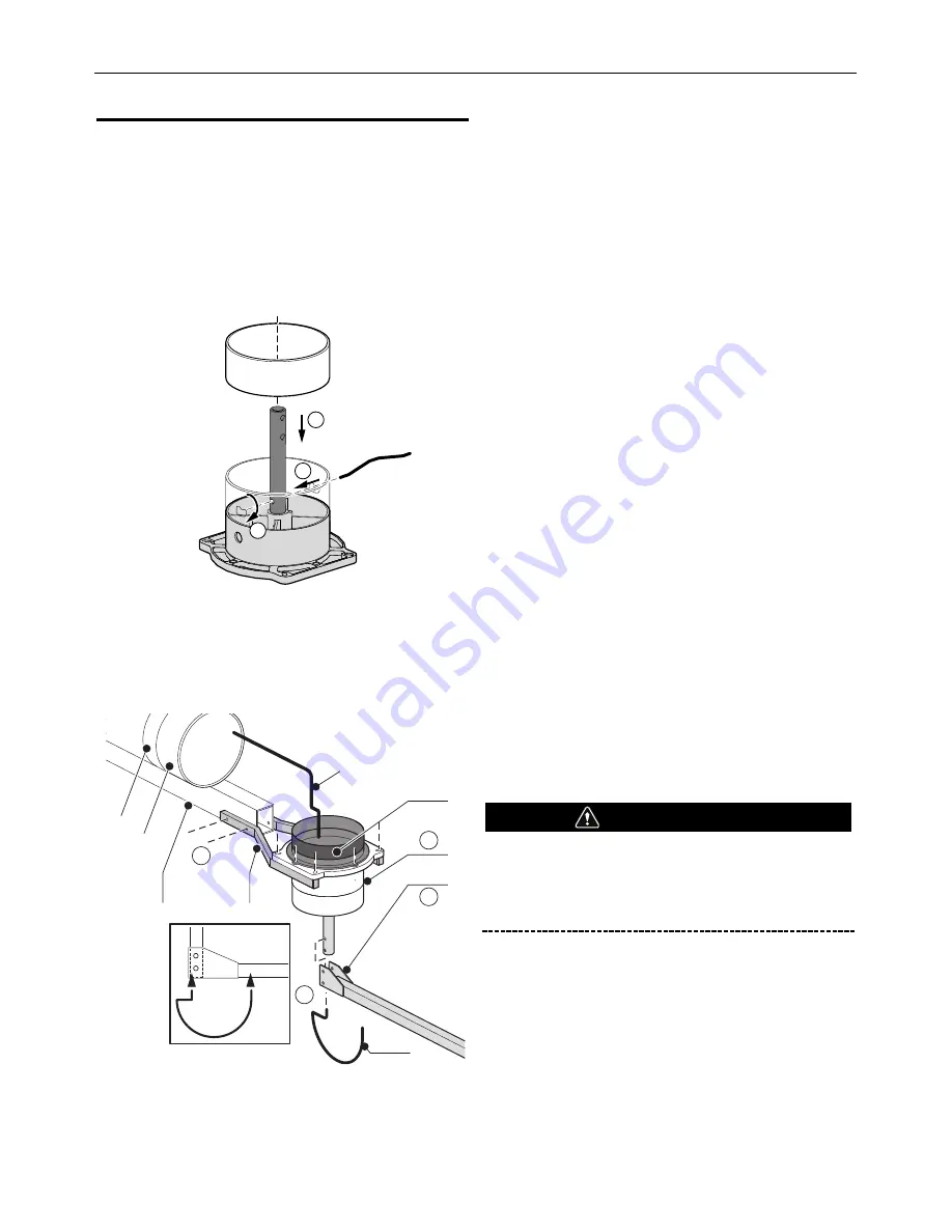
13.) Mount the (2) Arm Mounting Brackets
(Figure A.43, Item B) using the (2) 5/16-18 UNC, 5.00”
long bolts with nuts.
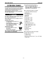
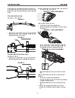
14). The Extraction Arm’s Rotating Hinge consists of three
pieces: The metal base swivel mount, red plastic ring
and clamping pin. Note: these items are packaged with
the LFA 3.1 and LFA 4.1 extraction arms.
See Figure A.42.
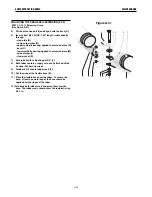
Mount the red plastic ring to the metal base swivel
mount by fitting the clamping pin through the hole in
the rotating rod, and snapping it into place on the
U-shaped indents on the red plastic ring. The lip of the
ring should fit securely against the top edge of the base
swivel mount, yet rotate with the rod.
The assembly should look like Item D in Figure A.43.
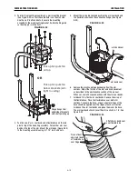
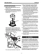
15.) Mount the Rotating Hinge (D) on the Arm Mounting
Brackets using the (4) 5/16-18UNC, 2.25” long, (4)
washers and (4) nuts. Make sure the cable hole is
positioned in the back, pointing toward the crane rail.
16.) Remove protective paper from the self-adhesive foam
seal and attach the foam seal onto the base swivel
mount. The foam which is sandwiched between the
base swivel mount and the tapered connection flange
will help to make the system airtight.
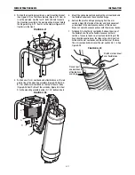
Mount the tapered connection flange (C) onto the base
swivel mount using (2) 5/16-18x1.75 HHCS, (2) 5/16-
18x2.50 HHCS, (6) washers and (4) nuts.
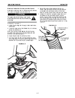
17.) Fold back 2/3 of the rubber seal.
18.) Cut the wrap of the flexible hose and place one end of
the flexible hose over the tube. To secure the hose, at
least one metal ring of the hose should be applied over
the ridges at the tube.
19.) Fold back the rubber seal and place it over the hose.
The rubber seal should cover 0.5 to 1 inch of the tube.
20.) Place the Distance Spring (K) in the clamping bush in
the middle section of the base swivel mount. Feed the
other end of the Distance Spring into the open end of
the flexible hose.
21.) Secure end of hose to inlet ring with hose clamp.
22.) Place a rubber seal over the lower part of the tapered
connection flange (D) and fold back 2/3 of the rubber
seal.
23.) Place the lose end of the flexible hose over the lower
part of the tapered connection flange and secure the
hose with rubber seal.
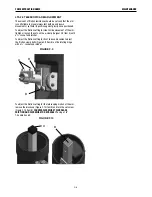
24.) Turn the hinge rod so the long side of the stop pin at its
base points away from the wall, and mount the hanging
adapter (Fig. A.42, Item E) to the hinge rod using the (2)
2.25” bolts with nuts.
25.) Mount the spring bracket (Figure A.42, Item F) into the
two holes as shown.
Leave the tape and plastic packaging on the extraction arm
sections until the arm is completely installed (including
mounting the hood). The arm is spring-balanced and will
spring out quickly if not mounted securely with the hood in
place.
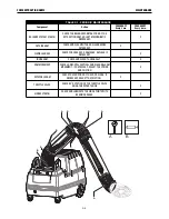
26.) Adjust the friction resistance of the swinging motion of
the extension crane according to maintenance section.
27.) Use the rubber seals and connecting hoses to close all
gaps between arm sections on the Extension Crane and
the Extraction Arm.
At this stage, the LFA 3.1 or LFA 4.1 extraction arm can be
mounted onto the extension crane. Please refer to the
extraction arm instruction manual for the next steps.
CAUTION
2
1
3
Figure A.42
C
D
E
B
A
F
1
4
2
3
I
J
K
Figure A.43
Summary of Contents for K1655-10-LTA 2.0
Page 43: ...ii THIS PAGE INTENTIONALLY LEFT BLANK...
Page 61: ...P 968 C jpg LFA 4 1 K2633 7 General Assembly LFA 4 1 K2633 7 14 13...
Page 63: ...P 969 C jpg LFA 4 1 K2633 8 General Assembly LFA 4 1 K2633 8 14 13...
Page 64: ...ii THIS PAGE INTENTIONALLY LEFT BLANK...

