A-6
INSTALLATION
FUME EXTRACTION ARMS
MoUntinG tHe lfa 3.1 or 4.1 arM to tHe Wall-
MoUntinG bracKet
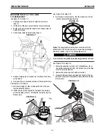
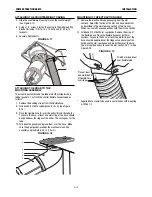
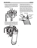
See Figure A.1 for steps 1-4
1. Cut through the upper cable tie to release the cotter pin
(Item A).
2. Lift the post of the base swivel mount by the lower cable tie.
3. Put the cotter pin through the lowest hole in the post (Item B)
and bend it around.
4. Cut the lower cable tie and let down the post.
FIGURE A.1
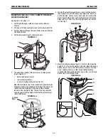
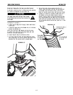
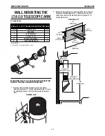
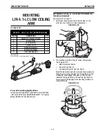
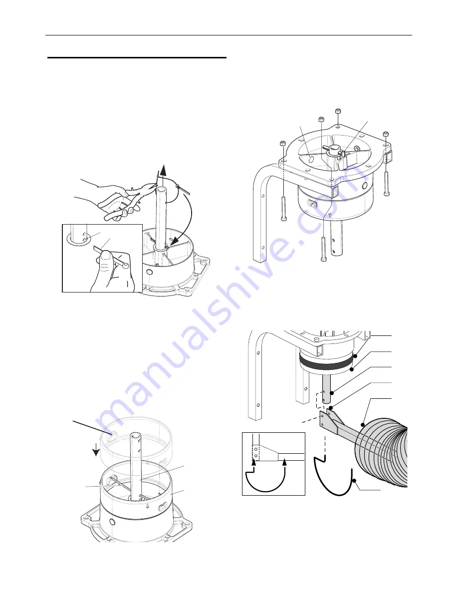
2. The mounting assembly of the arm comes in three pieces:
(See to Figure A.2)
•
Metal rotating rod (Item A),
•
red plastic ring (Item B),
•
and metal spring collar pivot rod (Item C).
Mount the red plastic ring to the metal mounting assembly by
fitting the metal spring collarpivot rod through the hole in the
rotating rod, and snapping it into place on the U-shaped
indents on the red plastic ring. The lip of the ring should fit
securely against the top edge of the mounting assembly yet
rotate with the rod.
FIGURE A.2
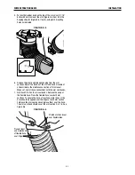
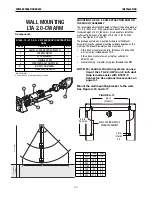
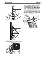
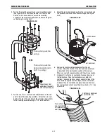
3. Position the mounting assembly on a wall mounting bracket
(See Figure A.3) so that the cable hole (Figure A.3, Item A) is
on the wall side. Use the four 3” bolts and nuts to secure the
mounting assembly to the wall mounting bracket. Rotate the
hinge rod (Fig. 3, Item D) so the stop pin (Figure A.3, Item B)
is in the front.
FIGURE A.3
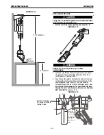
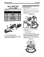
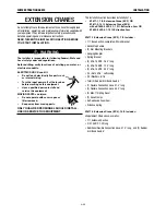
4. Mount the hanging adapter (Fig. A.4, Item D) to the hinge rod
using (2) 1.75” bolts with washers and nuts. Mount the spring
bracket (Fig. 5, Item F) into the two holes as shown. Position
one 8” rubber band (Fig. 5, Item A) and the flexible hose
supplied with the mounting bracket (Fig. 5, Item E) on the red
plastic ring of the rotating hinge.
FIGURE A.4
B
C
A
A
B
A
B
D
E
F
C
A
B
U-shaped
indent
Summary of Contents for K1655-10-LTA 2.0
Page 43: ...ii THIS PAGE INTENTIONALLY LEFT BLANK...
Page 61: ...P 968 C jpg LFA 4 1 K2633 7 General Assembly LFA 4 1 K2633 7 14 13...
Page 63: ...P 969 C jpg LFA 4 1 K2633 8 General Assembly LFA 4 1 K2633 8 14 13...
Page 64: ...ii THIS PAGE INTENTIONALLY LEFT BLANK...


