A-14
INSTALLATION
FUME EXTRACTION ARMS
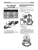
WALL MOUNTING THE
LTA 2.0 TELESCOPIC ARM
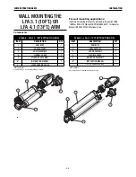
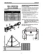
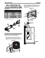
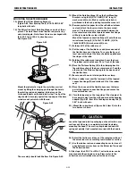
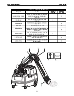
Components
*NOT SHOWN
See Parts Page for Hardware Bag Contents
MoUntinG tHe lta 2.0 telescopic eXtraction
arM on tHe Wall MoUntinG bracKet
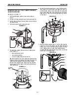
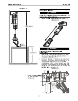
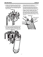
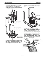
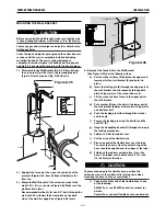
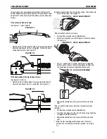
1. Disconnect the mounting bracket from the arm before
mounting by using a ½” wrench and loosening the U-clamp
(B) and sliding the post out of the friction tube (See Figure
A.20).
FIGURE A.20
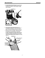
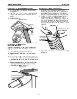
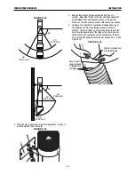
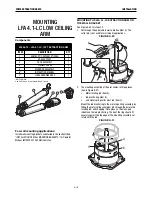
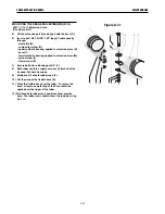
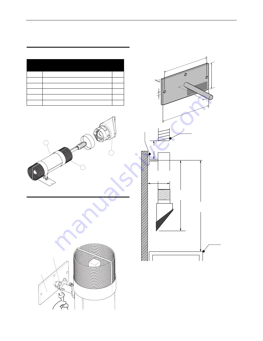
2. Mount the telescoping arm mounting bracket (A) to the wall.
Standard mounting height is 63” (1600mm) from the work
table to the center of the bracket. Refer to Figure A.21 for
drilling dimensions.
FIGURE A.21
K1655-10 – LTA 2.0 TELESCOPIC EXTRACTION ARM
ITEM
DESCRIPTION
QTY
1
ARM BODY
1
2
HOOD ASSEMBLY
1
3
FLEXIBLE HOSES
2
4*
INSTRUCTION MANUAL
1
5*
LOOSE HARDWARE BAG
1
%
$
11.8"
(300 mm)
38.6-54.3"
(980-1380 mm)
B
C
A
11.8-15.7"
(300-400 mm)
63"
(1600 mm)
4.7"
(120 mm)
10"
(255 mm)
9"
(230 mm)
0.4"
(10 mm)
8.3"
(210 mm)
ø0.5"
(ø13 mm)
Summary of Contents for K1655-10-LTA 2.0
Page 43: ...ii THIS PAGE INTENTIONALLY LEFT BLANK...
Page 61: ...P 968 C jpg LFA 4 1 K2633 7 General Assembly LFA 4 1 K2633 7 14 13...
Page 63: ...P 969 C jpg LFA 4 1 K2633 8 General Assembly LFA 4 1 K2633 8 14 13...
Page 64: ...ii THIS PAGE INTENTIONALLY LEFT BLANK...

