


English 7 English
Installation and Operator Instructions
General Description
Invertec 160TPX are constant current, continous control arc
welding power sources for stick and tig process. They
provide superior and reliable starting characteristics and arc
stability.
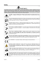
Read this entire section before installation or operation of
the machine.
Location and Environment
This machine will operate in harsh environments. However,
it is important that simple preventative measures are
followed to assure long life and reliable operation.
Do not place or operate this machine on a surface with
an incline greater than 15° from horizontal.
Do not use this machine for pipe thawing.
This machine must be located where there is free
circulation of clean air without restrictions for air
movement to and from the air vents. Do not cover the
machine with paper, cloth or rags when switched on.
Dirt and dust that can be drawn into the machine should
be kept to a minimum.
This machine has a protection rating of IP23. Keep it
dry when possible and do not place it on wet ground or
in puddles.
Locate the machine away from radio controlled
machinery. Normal operation may adversely affect the
operation of nearby radio controlled machinery, which
may result in injury or equipment damage. Read the
section on electromagnetic compatibility in this manual.
Do not operate in areas with an ambient temperature
greater than 40°C.
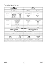
Input Supply Connection
The machines are a wide input voltage range: before
installing and turning it on, check the supplied input voltage,
phase, and frequency. The allowable input voltage range,
phase, and frequency are indicated in the technical
specification section of this manual and on the machine’s
rating plate. Be sure that the machine is grounded.
Make sure the power available at the input connection is
adequate for normal operation of the machine. The fuse
rating and cable sizes are both indicated in the technical
specification section of this manual.
Input Supply From Engine Driven Generators
The machine is designed to operate on engine driven
generators as long as the auxiliary can supply adequate
voltage, frequency and power as indicated in the "Technical
Specification" section of this manual. The auxiliary supply
of the generator must also meet the following conditions:
Vac peak voltage: below 410V.
Vac frequency: in the range of 50 and 60Hz.
RMS voltage of the AC waveform:
230vac ± 15%.
It is important to check these conditions because many
engine driven generators produce high voltage spikes.
Operation of this machine with engine driven generators not
conforming to these conditions is not recommended and
may damage the machine.
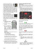
Output Connections
A quick disconnect system using Twist-Mate
cable
plugs is used for the welding cable connections. Refer
to the following sections for more information on
connecting the machine for operation of stick welding
(MMA) or TIG welding (GTAW).
(+) Positive Quick Disconnect: Positive output
connector for the welding circuit.
(-) Negative Quick Disconnect: Negative output
connector for the welding circuit.
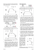
Stick Welding (MMA)
This machine does not include a MMA welding kit
cables, but may be purchased separately. Refer to the
accessories section for more information.
First determine the proper electrode polarity for the
electrode to be used. Consult the electrode data for this
information. Then connect the output cables to the
output terminals of the machine for the selected polarity.
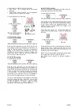
Shown here is the connection method for DC(+) welding.
Connect the electrode cable to the (+) terminal and the
work clamp to the (-) terminal. Insert the connector with
the key lining up with the keyway and rotate
approximately ¼ turn clockwise. Do not over tighten.
For DC(-) welding, switch the cable connections at the
machine so that the electrode cable is connected to (-)
and the work clamp is connected to (+).
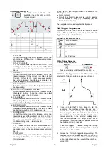
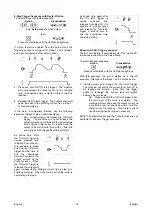
TIG Welding (GTAW)
This machine does not include a TIG torch necessary for
TIG welding, but one may be purchased separately.
Refer to the accessories section for more information.
Most TIG welding is done with DC(-) polarity shown
here. If DC(+) polarity is necessary switch the cable
connections at the machine.


