REMOTE CONTROL
The Dual Maverick
®
450 is equipped with a 6-pin and a 14-pin
connector. The 6-pin connector is for connecting the K857 or
K857-1 Remote Control or for TIG welding, the K870 foot Amptrol
or the K963-3 hand Amptrol. When in the CC-STICK, ARC
GOUGING, TIG or CV-WIRE modes and when a remote control is
connected to the 6-pin Connector, the auto-sensing circuit
automatically switches the OUTPUT control from control at the
welder to remote control.
The 14-pin connector is used to directly connect a wire feeder
control cable. In the CV-WIRE mode, when the control cable is
connected to the 14-pin connector, the auto-sensing circuit
automatically makes the Output Control inactive and the wire
feeder voltage control active.
In each case, once connected control maybe optionally changed
back to the control panel using the display remote button. The
maximum and minimum current range can be setup / modified in
display.
NOTE: When a wire feeder with a built in welding voltage
control is connected to the 14-pin connector, do not
connect anything to the 6-pin connector.
AUXILIARY POWER RECEPTACLES
For heavy loads switch the "HIGH IDLE/RUN-STOP" control switch
to the "High Idle" mode and set weld output at max.
The auxiliary power of the Dual Maverick
®
450 consists of two
220 VAC European (IEC-309) 15 Amp receptacles protected by two
15 Amp circuit breakers.
One 380 VAC European (IEC-309) 21 Amp receptacle that is
protected by a 25 Amp 3 Pole circuit breaker.
The auxiliary power capacity is 6,600 Watts Continuous of 50 Hz,
single phase power and 13,000 Watts continuous of 50 Hz, three
phase power.
STANDBY POWER CONNECTIONS
The Dual Maverick
®
450 is suitable for temporary, standby or
emergency power using the engine manufacturer’s recommended
maintenance schedule.
The Dual Maverick
®
450 can be permanently installed as a
standby power unit for 380 VAC, three phase, 21 amp service.
Connections must be made by a licensed electrician who can
determine how the power can be adapted to the particular
installation and comply with all applicable electrical codes.
Take necessary steps to assure load is limited to the capacity of
the Dual Maverick
®
450.
CABLE INDUCTANCE AND ITS EFFECTS ON
WELDING
Excessive cable inductance will cause the welding performance to
degrade. There are several factors that contribute to the overall
inductance of the cabling system including cable size, length, and
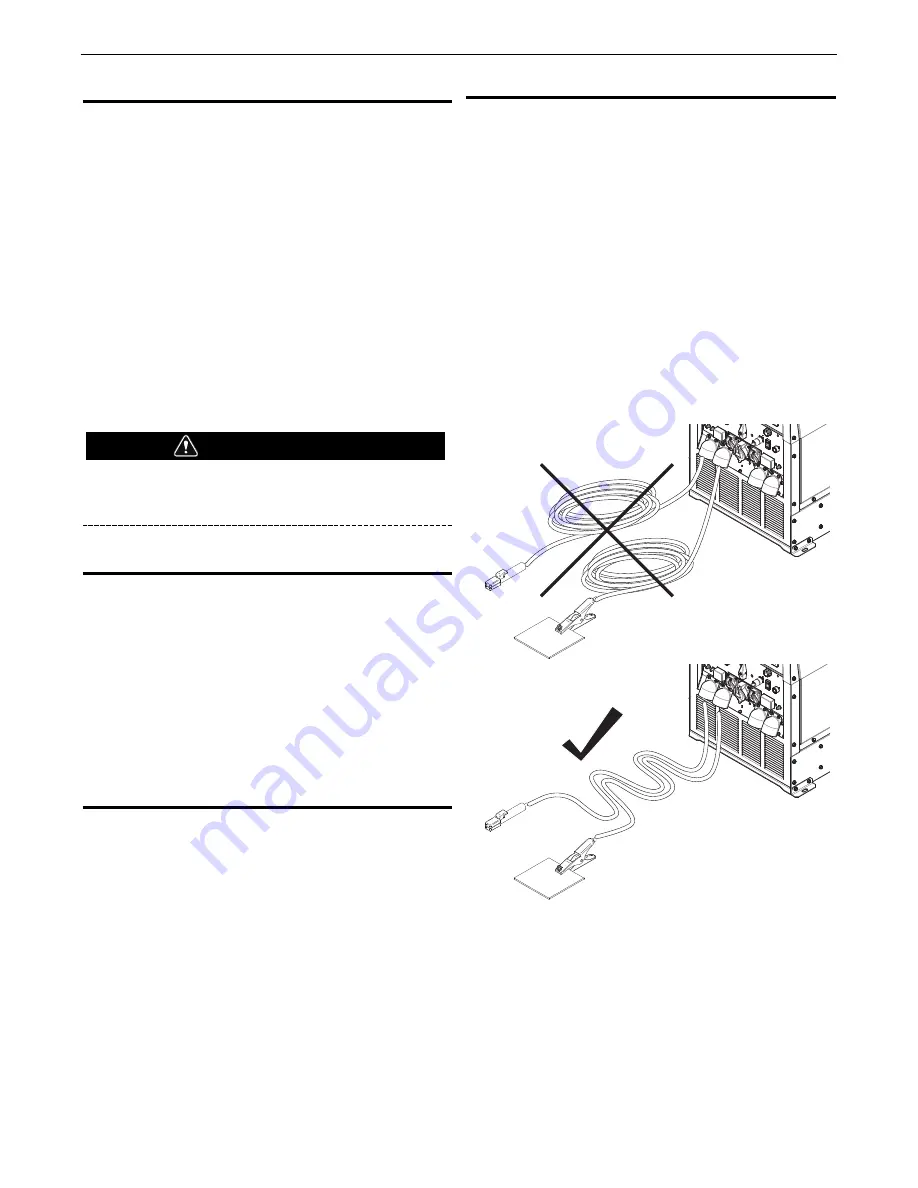
number of loops. To reduce cable inductance do not loop welding
cables see figure A.4, especially consistently in one direction. If
there are loops separate them as much as possible and make the
loop as large as possible. A straight or zig-zag pattern between
the machine and work is recommended see figure A.4.
If a spooling mechanism is used to store the welding cables,
unspool the cables. Avoid leaving more than 30 feet of cable on
each storage spool. For best performance completely unspool the
welding cables.
For optimal performance when welding with two operators
maintain some distance between the left and right sets of welding
cables and use individual work piece cables.
FIGURE A.4
WARNING
Work Lead
Electrode
Work Lead
Electrode
A-9
INSTALLATION
DUAL MAVERICK
®
450


