background image

5

SAFETY MARK:  This equipment is suitable for supplying power for welding operations carried out in
an environment with increased hazard of electric shock.

Installation and Operator Instructions

Read this entire section before installation or operation
of the machine.

Location and Environment

This machine will operate in harsh environments.
However, it is important that simple preventative
measures are followed to assure long life and reliable
operation.


Do not place or operate this machine on a surface
with an incline greater than 15° from horizontal.


This machine must be located where there is free
circulation of clean air without restrictions for air
movement to and from the air vents.  Do not cover
the machine with paper, cloth or rags when
switched on.


Dirt and dust that can be drawn into the machine
should be kept to a minimum.


This machine has a protection rating of IP21.  Keep
it dry when possible and do not place it on wet
ground or in puddles.


Locate the machine away from radio controlled
machinery.  Normal operation may adversely affect
the operation of nearby radio controlled machinery,
which may result in injury or equipment damage.
Read the section on electromagnetic compatibility in
this manual.


Do not operate in areas with an ambient
temperature greater than 40°C.

Input Supply Connection

Check the input voltage, phase, and frequency supplied
to this machine before turning it on.  The allowable input
voltage is indicated in the technical specification section
of this manual and on the rating plate of the machine.
Verify the connection of grounding wires from the
machine to the input source.

The frame of this machine must be grounded. A ground
terminal located on the base of the generator is provided
for this purpose.

This machine is factory 3ph-400V connected. To
connect it in 3ph-230V, remove the left case panel of the
machine to have access to the input reconnect panel.
Modify the connections according to the connection
diagram located on the inside of the case side and
shown below.

Recommended input wire and fuse
sizes

Input voltage/

frequency

Input circuit

fuse

(FM = 60%)

Recommended

input wire size

Fuse

230 V / 50 Hz
400 V / 50 Hz

60A
34A

4x10 mm

2

4x10 mm

2

100A

60A

Operation

General description :
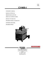
The CV405-I is a constant voltage DC power source
designed for the GMAW and FCAW processes.  It is
available with :


42 VAC/10 amp auxiliary power for the wire feeder.


230 VAC/ 3.5 amp auxiliary power for water cooler.

For a quick and easy handling within the welding area, it
is factory mounted on a built-in undercarriage equipped
with a  platform for a gas cylinder.  Recommended wire
feeders: LF30/31, LN-25, LN-27.

Controls on the case front

A.  ON/OFF power switch (O/I) :  It controls the input

power to the machine. Be sure the power source is
connected to the mains supply before turning power
on ( "I").

B.  Power indicator light :  Indicates the power is on.
C.  Thermal indicator light :  It indicates the machine is

overloaded or if cooling is not sufficient.

D.  High inductance negative output connection :  The

high inductance connection is more suitable for short
arc welding heavier weldments or when using 75%
Argon / 25% CO

2

 shielding gas. This connection

produces a softer arc and a flatter bead with more
wash-in than the low inductance connection. A spray

Summary of Contents for CV405-I

Page 1: ...NUNGSANLEITUNG MANUAL DE INSTRUCCIONES MANUEL D UTILISATION BRUKSANVISNING OG DELELISTE GEBRUIKSAANWIJZING BRUKSANVISNING LINCOLN ELECTRIC FRANCE Avenue Franklin Roosevelt 76121 Le Grand Quevilly cede...

Page 2: ...ve den folgenden Bestimmungen entspricht es conforme con las siguientes directivas Est conforme aux directives suivantes er i samsvar med f lgende direktiver Overeenkomt conform de volgende richtlijne...

Page 3: ...tromagn tique CEM 27 CV405 I Caract ristiques Techniques 28 INNHOLD Sikkerhetsregler 29 Installasjon og brukerveiledning 30 Elektromagnetisk Kompatibilitet EMC 32 CV 405 I Tekniske spesifikasjoner 32...

Page 4: ...SION Remove fire hazards from the welding area and have a fire extinguisher readily available Welding sparks and hot materials from the welding process can easily go through small cracks and openings...

Page 5: ...machine Verify the connection of grounding wires from the machine to the input source The frame of this machine must be grounded A ground terminal located on the base of the generator is provided for...

Page 6: ...el J Cable clamp for input cables K Circuit breaker Protects the 230V auxiliary circuit from overloads and shorts If this breaker opens the CV405 I will work normally however equipment powered by the...

Page 7: ...than 1 ohm check the wiring back to the main transformer If they are less than 1 ohm refer to Procedure for replacing PC boards Checking Snubber Circuit In case of an SCR malfunction or failure the sn...

Page 8: ...10 3 phase 400V 10 3 phase Input Power at Rated Output 18kW 100 FM 21kW 60 FM Frequency 50 60 Hertz Hz IDLE POWER 800 VA RATED OUTPUT Duty Cycle EN60974 1 Based on a 10 min period 60 100 Output Curren...

Page 9: ...j lpares hud Skydda personal i n rheten med en l mplig sk rm av icke br nnbart material och varna dem s att de inte tittar p ljusb gen eller exponerar sig f r ljusb gens str lning SVETSSPRUT KAN ORSAK...

Page 10: ...p v t mark eller i vattenp lar Placera inte maskinen i n rheten av radiostyrd utrustning ven vid normal anv ndning kan funktionen hos radiostyrd utrustning st ras allvarligt vilket kan leda till olyc...

Page 11: ...g av svetsstr m till matarverket vid tr d Alt f r terledaren vid tr d G Uttag f r matarverk 14 polig Amphenolkontakt f r matarverkets mellankabel H 42 Volt automats kring Skyddar 42 voltskretsen i mat...

Page 12: ...ontrollkort Utf r f ljande fels kning innan styrkortet byts ut 1 Koppla bort maskinen fr n eln tet 2 Kontrollera s att anslutningarna i kretskortets kontakter inte r l sa speciellt J3 3 Lossa kontakte...

Page 13: ...r risker f r utrustning och personal Att anv nda sk rmade kablar inom arbetsomr det kan reducera den elektromagnetiska str lningen Detta kan bli n dv ndigt f r vissa speciella till mpningar CV405 I Te...

Page 14: ...S51590 4 Rear wheel 2 S51238 Cap 2 S51239 Axle 1 3 S51600 2 Front wheel 2 4 L50731 1 Transformer 230 400V 1 5 M51401 1 Coil 1 6 M51566 Mounting coil 1 7 M51535 1 Rectifier bridge 1 8 M51543 Left moun...

Page 15: ...onte raddrizzatore 1 8 M51543 Supporto sinistro 1 M51544 Supprto destro per raddrizz cond 1 9 L50759 Induttanza PFC 1 10 FP 1051D Assieme pannello frontale 1 11 S52108 Scheda controllo 1 L50733 Pannel...

Page 16: ...20 Circuit breaker 10 amp 250V 1 9 M51012 2 ON OFF switch 1 10 M51088 ON OFF light 1 Note The thermal indicator light is included on the control PC board Parti di ricambio Rif N parte Descrizione N 1...

Page 17: ...53 Electrical Schematic Schema Elettrico Elektrische Schaltpl ne Esquema El ctrico Sch ma Electrique Elektrisk Skjema Elektrisch Schema Elektriskt Kopplingsschema...

Page 18: ...delli raffreddati ad acqua Refrigerador Magnum 10 I equipado de f brica para modelos con refrigeraci n por agua Refroidisseur Magnum 10 I livr en standard pour la version refroidie eau Magnum Wasserk...

Page 19: ...4 76121 LE GRAND QUEVILLY CEDEX TEL 02 32 11 40 40 FAX 02 32 11 40 11 FAX BUREAU COMMERCIAL 02 32 11 40 12 FAX EXPORT DEPARTMENT 02 32 11 40 08 FAX SERVICE APRES VENTES AFTER SALES DEPARTMENT 02 32 11...

Reviews: